These FAQ's apply to the following current production diagnostic tools and families across multiple markets. All tools listed may not be available in your market.
TRITON Family, APOLLO- Family, MODIS Family, SOLUS Family, P1000, VANTAGE Family, ETHOS Family
Use the filtered Search function above to search for keywords on this FAQs page.
All information is intended as typical. For specific instructions, see the applicable section in this manual. Not all diagnostic tools listed within these FAQs are available in all markets.
Click on an image to expand, click again to reset size. Does not apply to all images/illustrations.
|
Category |
FAQ's |
|||||||||||||||||||||||||||||||||||||||||||||||
|---|---|---|---|---|---|---|---|---|---|---|---|---|---|---|---|---|---|---|---|---|---|---|---|---|---|---|---|---|---|---|---|---|---|---|---|---|---|---|---|---|---|---|---|---|---|---|---|---|
| Getting Started |
See Getting Started at the top of the main menu in this User Manual application. |
|||||||||||||||||||||||||||||||||||||||||||||||
| Accessories |
To find accessories, contact your Snap-on representative and/or visit Diagnostic Tools and Accessories |
|||||||||||||||||||||||||||||||||||||||||||||||
| Accessories |
To find screen protectors, contact your Snap-on representative and/or visit Diagnostic Tools and Accessories NOTE - Screen protectors are not available for all models.
|
|||||||||||||||||||||||||||||||||||||||||||||||
| ADAS |
Most all ADAS recalibrations are performed using the Scanner function on your diagnostic tool. Select Scanner, then choose the applicable vehicle system and navigate to the desired function or test. NOTE - Some ADAS tests are displayed on top level menus, so be sure to scroll through the complete menu during navigation. Depending on the vehicle and recalibration test, special recalibration equipment may be required. For additional information about Snap-on ADAS recalibraiton equipment visit EZ-ADAS Hub. ADAS Recalibration Report Form Depending on the vehicle (if supported), an ADAS Recalibration Report form may be available after performing an ADAS recalibration test. The ADAS Recalibration Report form allows you to print the form with your shop information, the vehicle’s VIN, odometer and license plate information. The recalibration information is manually entered after the form is printed. Sample ADAS Report When an ADAS report is generated, press the SAVE icon to automatically uploaded it to the Snap-on Cloud. From the Cloud you can print or share the report. For additional information, see Snap-on Cloud. EZ-ADAS Recalibration instructions and user guides are integrated within the Mobile APP and website at EZ-ADAS Hub Important notes about ADAS and diagnostic tools: Supported ADAS recalibrations and tests vary by vehicle make/model. Before performing any ADAS recalibraiton always make sure: You have the vehicle identified correctly You are using the correct special equipment as applicable to the specific vehicle You follow all instructions and safety precautions as specified |
|||||||||||||||||||||||||||||||||||||||||||||||
| Battery / Device Power |
If your diagnostic tool uses a rechargeable type battery pack (e.g. APOLLO Family, TRITON Family, etc), the tool will turn on and operate when connected to a OBD-II vehicle using the data cable (power is supplied via the vehicle DLC). Even though this is possible, it is not recommended. You should always have the correct battery pack installed and charged in the tool during operation. The diagnostic tool can also be powered from a standard AC outlet using the AC power supply that comes with the tool. |
|||||||||||||||||||||||||||||||||||||||||||||||
| Battery / Device Power |
Yes- The diagnostic tool is designed to be powered from the vehicle. All OBD-II/EOBD vehicles have vehicle battery power (B+) available on the data link connector (DLC). The diagnostic tool is powered through the Data Cable when connected to the vehicle DLC |
|||||||||||||||||||||||||||||||||||||||||||||||
| Battery / Device Power |
Battery charging occurs whenever the data cable is connected to a live vehicle DLC, or when the AC power supply is used and connected to a live AC power source. |
|||||||||||||||||||||||||||||||||||||||||||||||
| Battery / Device Power |
For more information, contact your Snap-on representative and/or visit Diagnostic Tools and Accessories Only use the manufacturer recommended original equipment replacement battery pack. |
|||||||||||||||||||||||||||||||||||||||||||||||
| Battery / Device Power |
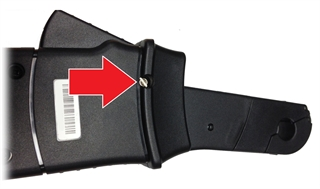
The Battery Status Indicator LED (located next to the power supply jack) indicates battery status.
|
|||||||||||||||||||||||||||||||||||||||||||||||
| Battery / Device Power |
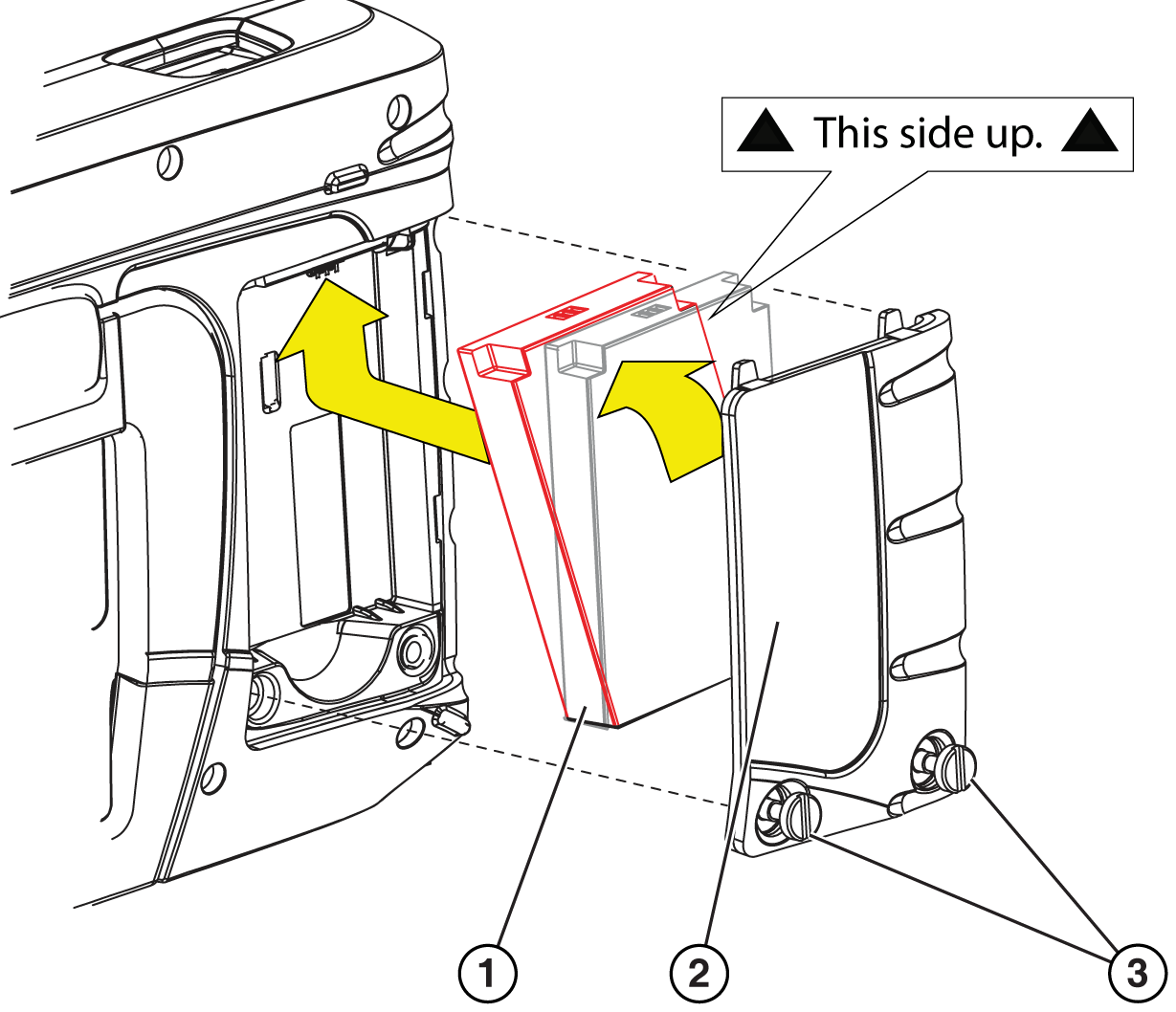
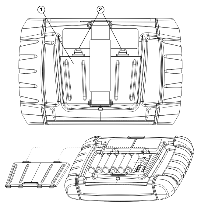
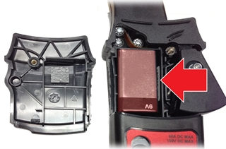
Typical battery pack replacement: (for specific tool instructions, see Main Menu >General Information > The Battery Pack)
Typical Battery Pack Illustration shown.
|
|||||||||||||||||||||||||||||||||||||||||||||||
| Battery / Device Power |
Make sure you are using a known good power source, and then try the following:
If you are still experiencing difficulties, contact customer support Phone
|
|||||||||||||||||||||||||||||||||||||||||||||||
| Battery / Device Power |
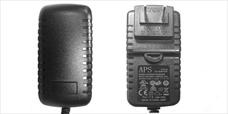
All the diagnostic tool listed below use power supply Snap-on P/N 2-60666A. Original Mftr Information - APS P1415 AC Adapter Model: KSAS0251500200D5 Specs:
TRITON-D10 TRITON-D8 APOLLO-D9 APOLLO-D8 MODIS Edge MODIS Ultra SOLUS Edge SOLUS Legend SOLUS Ultra P1000 VANTAGE Legend VANTAGE Ultra ETHOS Edge* ETHOS Tech* ETHOS PRO* ETHOS PLUS*
* Also require Snap-on Power Adapter (HD26 to DC plug) P/N EAC0069B26A
Not all scan tool AC adapters are compatible. Using the incorrect AC adapter can prevent the battery from charging or cause issues during software upgrade installations. For more information, contact your Snap-on representative and/or visit Diagnostic Tools and Accessories |
|||||||||||||||||||||||||||||||||||||||||||||||
| Battery / Device Power |
The ETHOS Plus, ETHOS PRO and ETHOS Tech use standard AA batteries for power when not connected to a vehicles powered OBD-II port or to an AC power source. When replacing the Diagnostic Tool batteries, use Alkaline or rechargeable nickel-metal hydride (NiMH) type AA batteries only. Do not use standard (lead/zinc) batteries as they do not provide sufficient power to operate the Diagnostic Tool, and may leak and damage the Diagnostic Tool. To replace the batteries: Depress the two battery cover lock tabs and lift off the battery cover Remove the old batteries Observing proper polarity (shown on the battery slots), install six new AA batteries IMPORTANT: Your Diagnostic Tool can be damaged if the battery polarity is incorrect. Refer to the diagram in the battery compartment on the rear of the tool for correct battery polarity. Fit the battery cover onto the housing. NOTE: If installing rechargeable batteries, be sure to reset the battery type on the Tools Setup menu. This helps prolong the life of the batteries, and notifies you when it is time to recharge them.
|
|||||||||||||||||||||||||||||||||||||||||||||||
| Component Testing |
This feature is only applicable with diagnostic tools that are equipped with a Scope/Meter (e.g. TRITON Family, MODIS Family, etc).
= Home Screen > Guided Component Tests Detailed instructions and reference information are provided to guide you through the testing process, from locating the component, to selecting the appropriate test, showing test lead connections, and illustrating electrical connector and pin configurations. In addition, the test meter is preconfigured for the selected test to save you time. Test results, including waveform examples, procedures, tips, and specifications may also be provided. |
|||||||||||||||||||||||||||||||||||||||||||||||
| Component Testing | ||||||||||||||||||||||||||||||||||||||||||||||||
| Vehicle Data Connection |
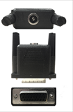
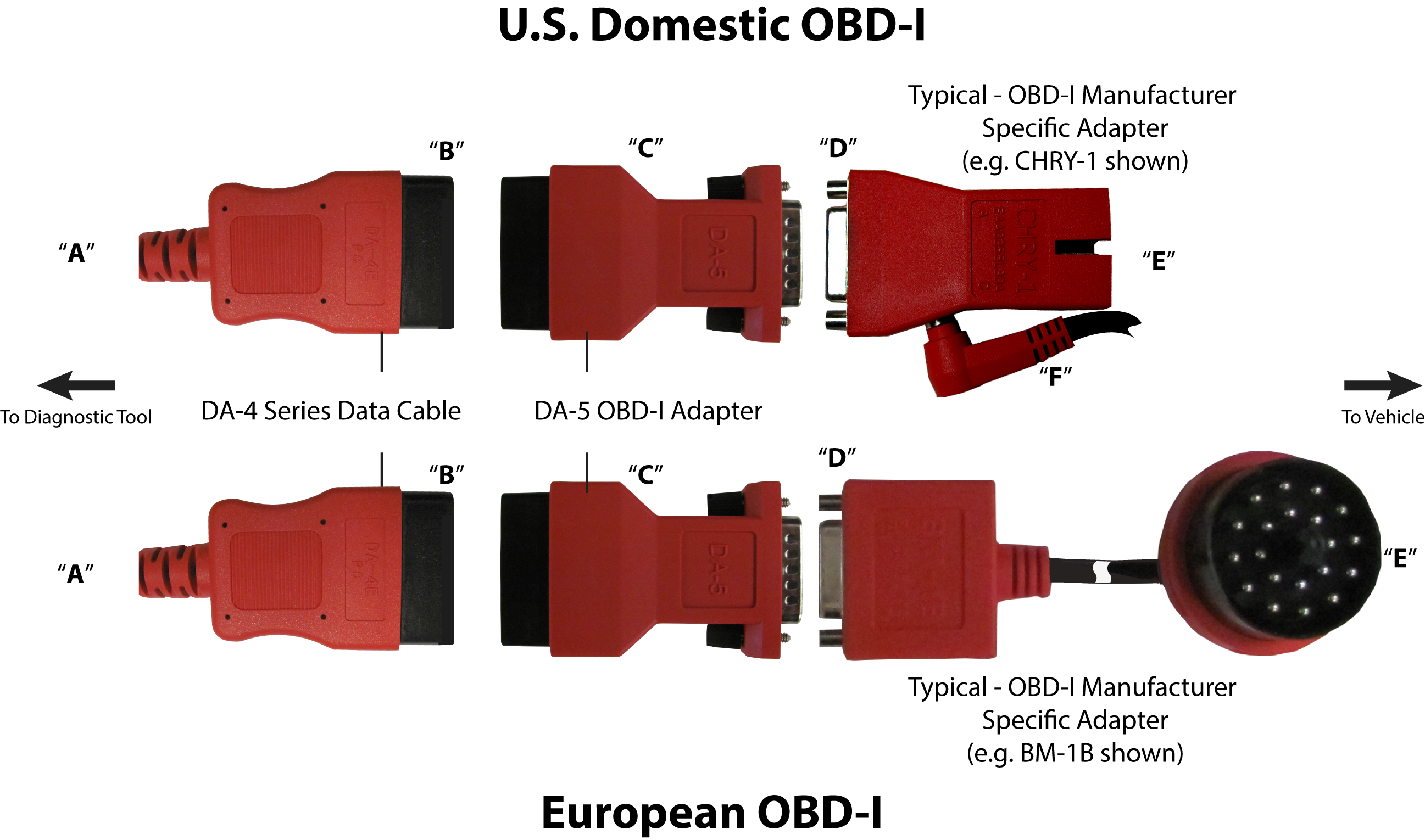
For most OBD-I (non-OBD-II/EOBD) compliant vehicles you can use the supplied data cable with the optional DA-5 adapter, and an optional manufacturer specific OBD-I adapter.
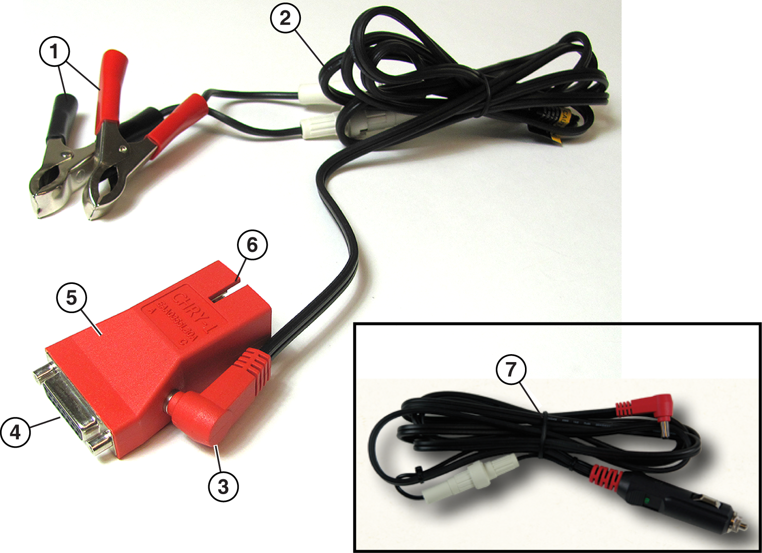
OBD-I adapters with a power jack MUST be connected to the vehicle battery using an accessory power cable “F”. If the OBD-I adapter does not have a power jack, an external power connection (accessory power cable) is not needed.
The image below shows a typical OBD-I adapter (with power jack). This type of adapter MUST be connected to the vehicle battery, using either of the power cables shown.
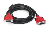
Only use original Snap-on data cables and accessories with your diagnostic tool. Total data cable length must not exceed 114.17 inches (2.9 meters)
For more information, contact your Snap-on representative and/or visit Diagnostic Tools and Accessories |
|||||||||||||||||||||||||||||||||||||||||||||||
| Vehicle Data Connection |
Ethernet equipped vehicles use the standard 16 pin OBD-II diagnostic link connector for diagnostic tool connection, however the diagnostic tool and/or data cable must be designed to support Ethernet communication. If your diagnostic tool and data cable are compatible with Ethernet communication, It will connect to the vehicle automatically. If your diagnostic tool and/or data cable are not compatible with Ethernet communication, when you try to connect you may be prompted to connect a special data cable. For example, "Use the DA-4EA Ethernet adapter cable. This vehicle is equipped with and Ethernet communications system. Please see your sales representative for more information." In order to communicate via Ethernet, follow the prompts on the diagnostic tool to use the data cable marked “DA-4E” or “DA-4EA” (current Part Number EAX0072L17A). Substituting a different data cable may result in no or an erroneous communication condition. Quick Tip Video, opens in a new tab. Snap-on supports Ethernet communication for select Jaguar, Land Rover and Volvo models. Supported Models as of 2021:
For more information, contact your Snap-on representative and/or visit Diagnostic Tools and Accessories |
|||||||||||||||||||||||||||||||||||||||||||||||
| Vehicle Data Connection |
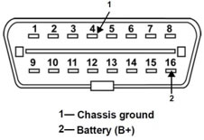
Start by checking the data cable to make sure it is fully seated and connected to the diagnostic tool and to the vehicle DLC. Where possible, connect to a different known good vehicle to test the operation. Then try to reestablish communication, by starting from the beginning and identify the vehicle to establish communication again. Make sure the vehicle you are trying to ID matches s the ID selection you chose If there is no change, make the following checks: Try a known good data cable. Check the vehicle DLC for damage, ensure the pins are connecting to the data cable, when it is connected. Test the vehicle DLC using the OEM service instructions, checking the power, ground and communication pins for operation. Typical OBD-II Data Link Connector (DLC) shown
OBD-II Applications - Make sure the vehicle is OBD-II compliant. Most 1996 and newer light duty vehicles are OBD-II compliant, however, the mere presence of the 16 pin OBD data link connector does not guarantee this. Some pre-1996 vehicles, medium duty vehicles, boats and even motorcycles have the 16 pin OBD data link connector but are not OBD-II compliant. OBD-I Applications - Make sure you are using the correct Personality Key and that it is not damaged. If the correct Personality Key is being used and the issue persists, attempt communication using a new Personality Key appropriate for use with the make of the vehicle. For example, on Ford use the K17 key in place of the K20. If communication can be established with the new key the original key has most likely failed and should be replaced. Please contact your local Snap-on Franchisee to order a replacement key. MICROSCAN - If using a MICROSCAN device, it remembers the last communication protocol used and will try using that protocol on the next vehicle if it has not powered down. Turn off the device between use to allow it to select the new correct protocol for the current vehicle. |
|||||||||||||||||||||||||||||||||||||||||||||||
| Vehicle Data Connection |
After identifying the vehicle using the VIN, the correct data cable and/or adapter will be displayed on the screen. Some vehicles have multiple DLCs, be sure to use the cable, adapter, and DLC the scan tool indicated on screen after identifying the vehicle. |
|||||||||||||||||||||||||||||||||||||||||||||||
| Vehicle Data Connection |
OBD-I - The vehicle may be providing insufficient B+ voltage and/or ground at the OBD-I DLC. If required, the Lighter Power Cable plugged into the OBD-I adapter (see Connecting to OBD-I vehicles) may be providing insufficient B+ voltage and/or ground. OBD-II - There may be insufficient B+ voltage and/or ground at the OBD-II DLC.
|
|||||||||||||||||||||||||||||||||||||||||||||||
| Vehicle Data Connection |
Chrysler Imports Stealth 1994-1996 Chrysler Imports Talon 1995-1998 Mitsubishi 3000GT 1994-1999 Mitsubishi Diamonte 1994-1996 Mitsubishi Eclipse 1995-1996 Mitsubishi Expo 1994-1996 Mitsubishi Galant 1994-1998 Mitsubishi Mirage 1994-1995 Mitsubishi Montero 1994 Chrysler Sebring 1995-2000 Dodge Avenger 1995-2000 Eagle Talon 1995-1999OBD-I |
|||||||||||||||||||||||||||||||||||||||||||||||
| Device Features |
Depending on your tool and the vehicle, you may be able to use the OBD-I European Vehicle Cable Adapter Kit. Contact your Snap-on representative for information. |
|||||||||||||||||||||||||||||||||||||||||||||||
| Device Features |
Depending on your device, market and subscription, information services will vary and /or not be available. Performance varies depending on your wireless network equipment and ISP. The following integrated information services provide up-to-date service/repair information directly to your diagnostic tool, via wireless network connection from our Snap-on Web Services Network:
If your access to these services has expired, or you have received messages about upcoming software upgrades or pending expiration, contact your sales representative. |
|||||||||||||||||||||||||||||||||||||||||||||||
| Device Features |
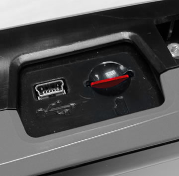
The MicroSD card is used to store operating system and user data files (e.g. screen captures and scanner data recordings). Do not remove the Micro SD card. The diagnostic tool will not operate without the MicroSD card installed. On select tools, the optional European Communication Software can also be loaded via MicroSD. The actual SD card is black in color, however for clarity it is shown in red in this image.
|
|||||||||||||||||||||||||||||||||||||||||||||||
| Device Features |
The Mini USB Jack is used to transfer saved data files to a personal computer using the ShopStream Connect companion application. |
|||||||||||||||||||||||||||||||||||||||||||||||
| Device Serial Number |
The diagnostic tool serial number is displayed on the System Information screen. Typical Navigation = Home Screen > Tools > System Information The diagnostic tool serial number is also located on the back of the diagnostic tool housing. |
|||||||||||||||||||||||||||||||||||||||||||||||
| Device Settings |
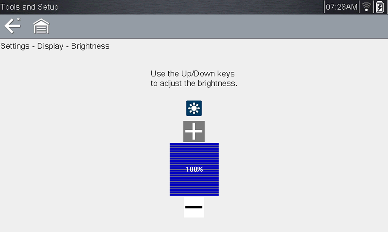
= Home Screen > Tools > Settings > System Settings > Display > Brightness Selecting this option opens the brightness setting screen for adjusting the back lighting of the display.
Each push of the Plus and Minus icons, or the up ( Select Back from the toolbar or press the N/X button to exit. |
|||||||||||||||||||||||||||||||||||||||||||||||
| Device Settings |
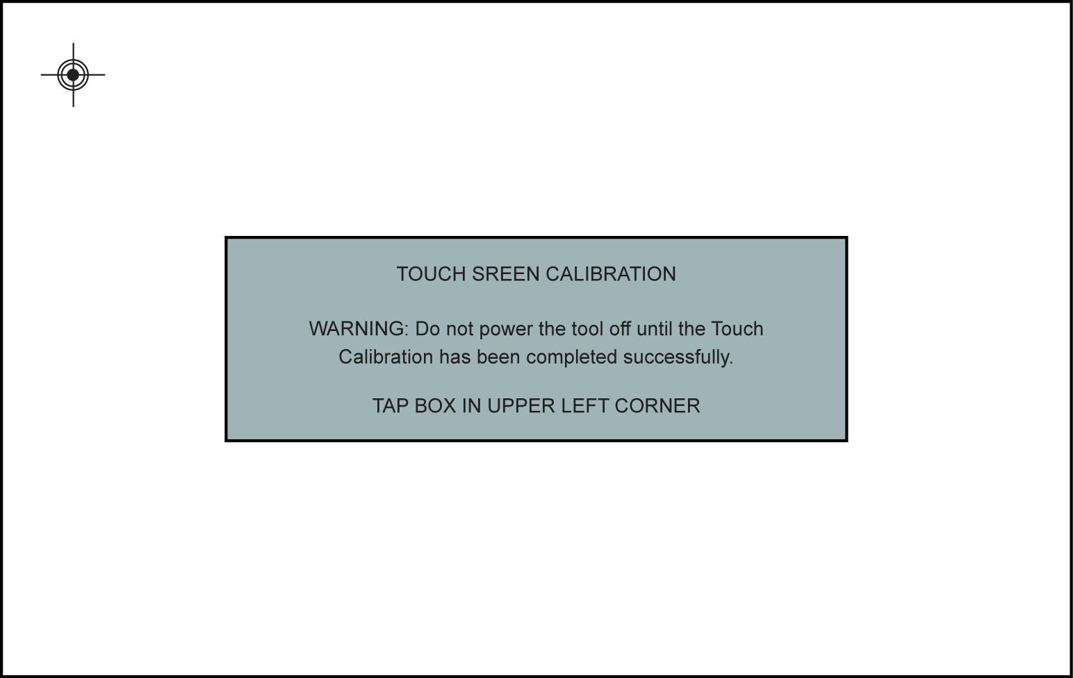
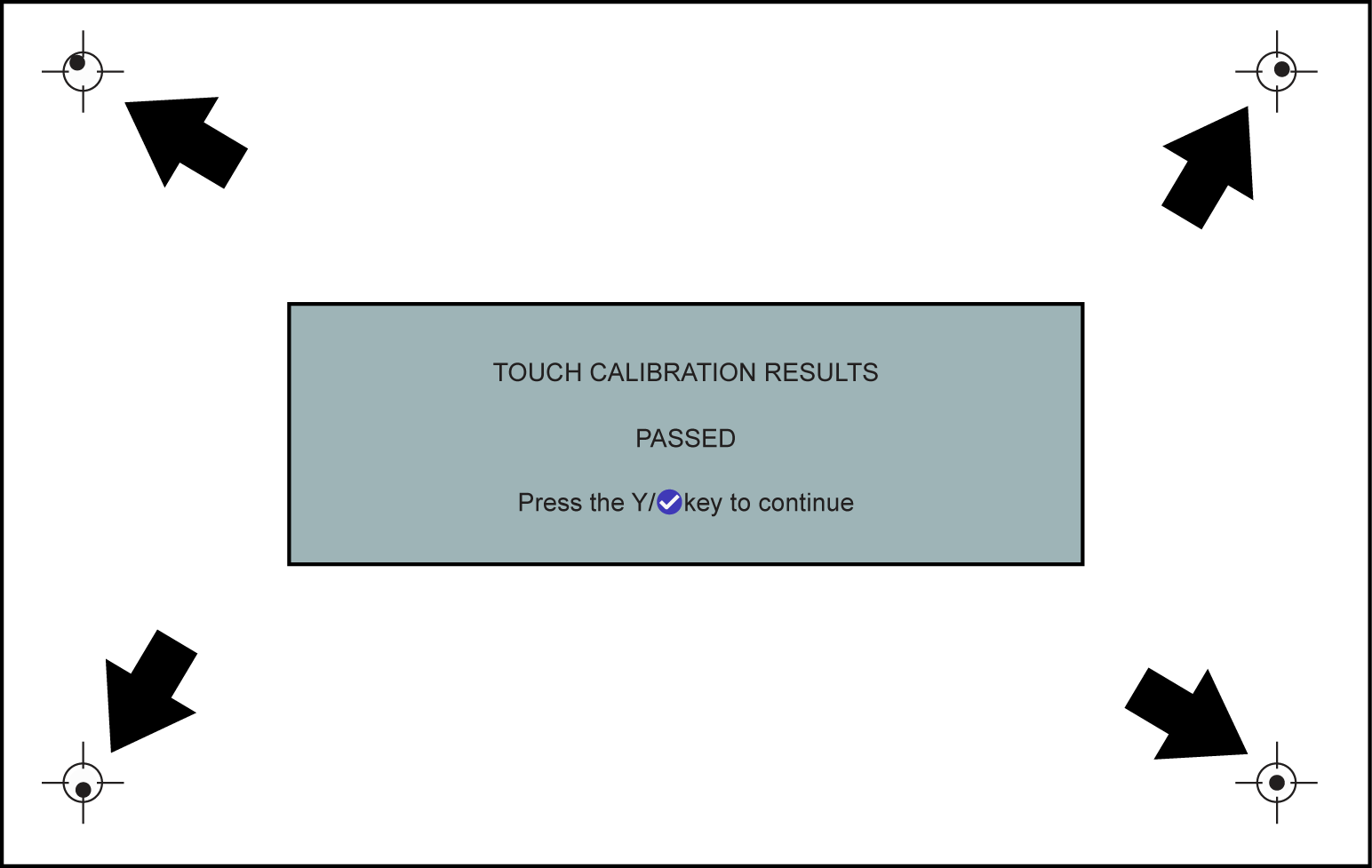
This feature is not applicable to all tools. Calibrating the touch screen maintains the accuracy of the touch-sensitive display. To avoid serious damage to the diagnostic tool, always complete the touch screen calibration sequence once it has begun. Never turn off the diagnostic tool while a screen calibration is in process. = Home Screen > Tools > Settings > System Settings > Display > Calibrate Screen The calibration screen
The results screen shows the entered calibration of each indicator. Ideal calibration would be to select each indicator exactly in the center, however selection inside the displayed circle is acceptable. If selecting the center is difficult using your finger, use a touch screen stylus (not included).
Touch screen calibration - Passed Result |
|||||||||||||||||||||||||||||||||||||||||||||||
| Device Settings |
= Home Screen > Tools > Settings > System Settings > Display > Color Theme This option allows you to select between a white and black background for the screen. The black background can be beneficial when working under poor lighting conditions. Day Theme (white background) Night Theme (black background).
Night Theme shown |
|||||||||||||||||||||||||||||||||||||||||||||||
| Device Settings |
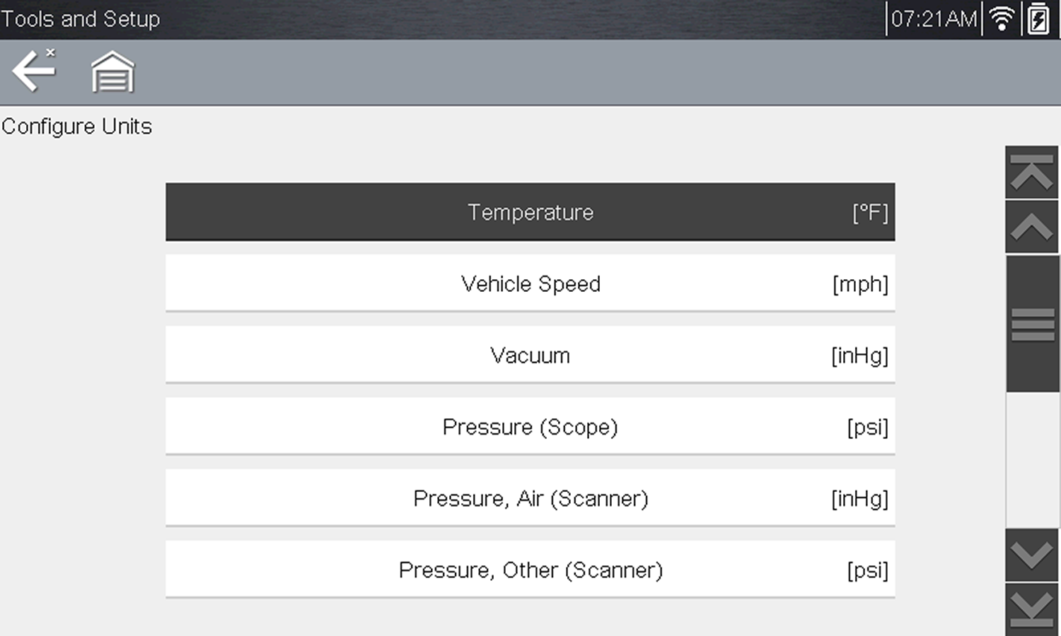
= Home Screen > Tools > Settings > Configure Units Choose between US customary or metric units of measure for various units of measure.
|
|||||||||||||||||||||||||||||||||||||||||||||||
| Device Settings |
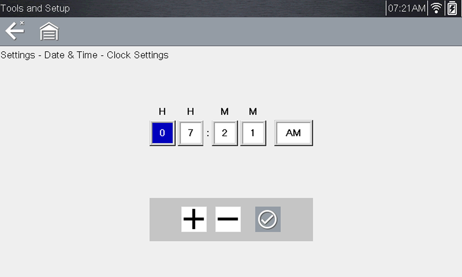
= Home Screen > Tools > System Settings > Date & Time Time Zone This option opens a menu of time zone settings. Scroll to highlight, then select the local time zone. The display returns to the Settings menu once a time zone is selected. Clock Settings This option opens a window for resetting the time on the real-time clock.
A warning message briefly displays followed by the Clock Settings screen.
Clock settings
Daylight Savings Time This option opens a menu to configure the internal clock for Daylight Savings Time. Choose from:
Make either selection, then select the Back icon or press the N/X button to return to the menu. Time Format This option determines whether time is displayed on a 12 or 24 hour clock. Selecting opens a menu with two choices:
Make either selection, then select the Back icon or press the N/X button to return to the menu. Date Format This option allows you to select how date information is displayed. Select from:
Make a selection, then select the Back icon or press the N/X button to return to the menu. |
|||||||||||||||||||||||||||||||||||||||||||||||
| Device Settings |
Typical Navigation = Home Screen > Tools > Configure Shortcut Key Configure the "S" button for Save Screen (when you press the "S" button it will save a bitmap image of the visible screen) |
|||||||||||||||||||||||||||||||||||||||||||||||
| Device Settings |
This feature allows you to change the function of the "S" (Shortcut) button. = Home Screen > Tools > Configure Shortcut Key Select a function from the menu to set your preference Options may vary:
|
|||||||||||||||||||||||||||||||||||||||||||||||
| Maintenance |
Periodically perform the following tasks to keep your diagnostic tool in proper working order:
Do not use any abrasive cleansers or automotive chemicals on the touch screen or housing. |
|||||||||||||||||||||||||||||||||||||||||||||||
| Motorcycle Scanning |
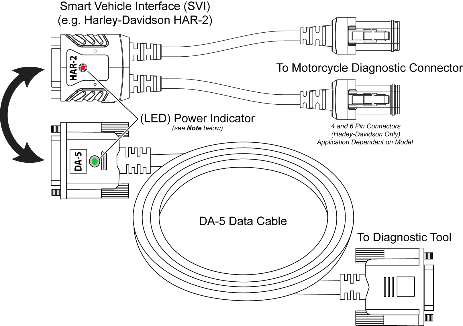
This feature is not applicable to all tools. Scanning a motorcycle is similar to scanning an automobile, however the data cable connection is different. Special data cables and adapters are required for the different motorcycle makes. Once connected the onscreen navigation is similar as well. This describes typical connection instructions. See the Motorcycle section for details. = Home Screen > Scanner > Motorcycle > [ID Motorcycle] > Engine > Codes On-screen data cable connection instructions are provided to connect the Smart Vehicle Interface (SVI) to the motorcycle diagnostic connector. The illustration shows a typical data cable connection using the supplied DA-5 data cable and the Harley-Davidson HAR-2 Smart Vehicle Interface (SVI). Other manufacturers connections are similar.
For more information on SVI cables, contact your Snap-on representative and/or visit Diagnostic Tools and Accessories Visit your Snap-on website store, or contact your Snap-on representative. |
|||||||||||||||||||||||||||||||||||||||||||||||
| OBD-II/EOBD Operations |
The OBD-II/EOBD function can be useful in a situation where the vehicle is not recognized or is an OBD-II compliant vehicle that is not supported by the enhanced scanner software, as you can still access “global” OBD-II/EOBD codes and data. You can also use it to:
|
|||||||||||||||||||||||||||||||||||||||||||||||
| OBD-II/EOBD Operations |
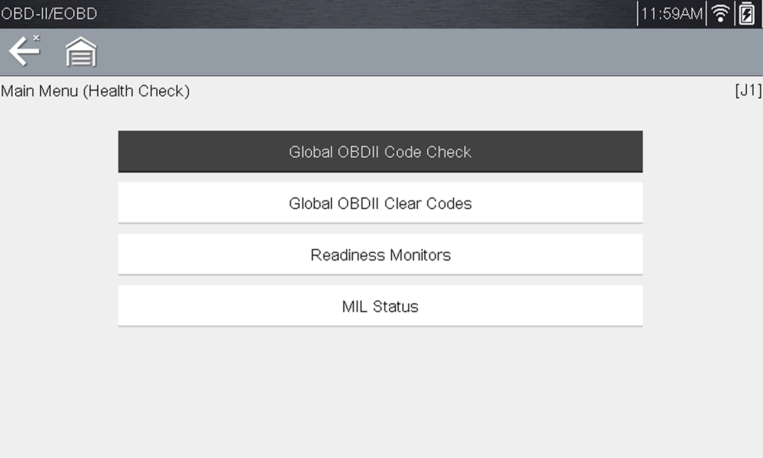
Using the OBD-II/EOBD Health Check function, you can quickly check / clear emissions-related diagnostic trouble codes (DTCs), and check readiness monitors for emissions testing. = Home Screen > OBD-II/EOBD > OBDII Health Check
OBD Health Check menu |
|||||||||||||||||||||||||||||||||||||||||||||||
| OBD-II/EOBD Operations |
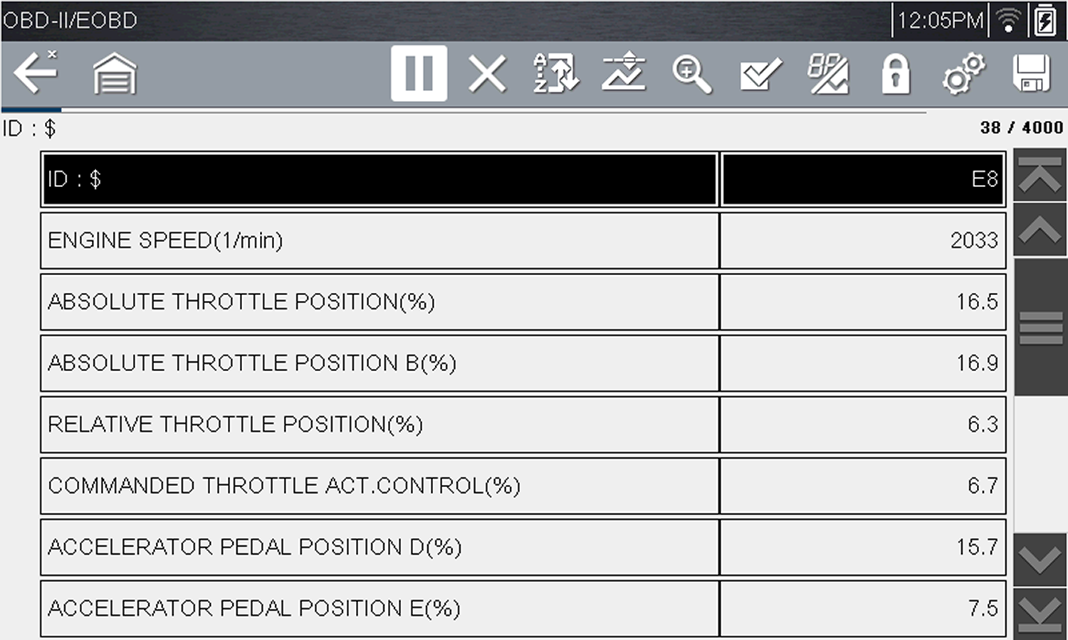
OBD-II (On-Board Diagnostics) provides a standardize “global” way to communicate with vehicle control modules/systems in order to check emission related components/systems for compliance. On-Board Diagnostics is basically the integrated “diagnostic” programming of the engine management system that monitors electrical sensors/components that influence exhaust emissions. OBD-II Service Modes (or services) provide the standardized emissions related data, test results and services that the engine management system monitors and are available without the use of a specialized diagnostic tool. There are basically ten basic modes / services. Brief descriptions are provided below. = Home Screen > OBD-II/EOBD > OBD Direct > OBD Diagnose > Start Communication Use this mode to view the current powertrain PIDs. This data is displayed unmodified as transmitted by the module(s). The main body of the screen has two columns; the left-hand column is a description of the PID and the right-hand column is the value or state. Viewing options and operations are the same as the Scanner function. Create a custom PID list to increase the display refresh rate / response time of displayed PIDs.
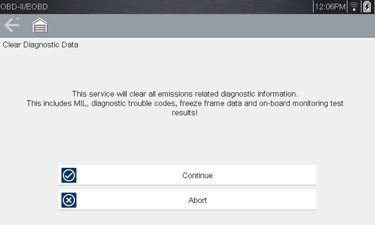
Current data display Freeze frame data provides a “snapshot” of critical PIDs at the approximate time the DTC was set. This mode is used to display freeze fame data for any stored emission related diagnostic trouble codes (DTCs). In most cases the stored frame is the last DTC that occurred. Certain DTCs, those that have a greater impact on vehicle emissions, have a higher priority. In these cases, the highest priority DTC is the one for which the freeze frame records are retained. This mode displays stored emission related DTCs. The display is similar to the Scanner function code display. The list does not include enhanced DTCs. This mode is used to clear all emission related diagnostic data, such as DTCs, freeze frame data, and monitor test results This also resets monitors to Not Ready and turns the MIL off.
A confirmation message displays to help prevent loss of any vital data.
Clear codes confirmation message
The screen updates several times as the memory is erased, then a “data has been cleared” message displays.
This option opens a submenu of services for to display parameters and test results from various sensors, monitor test results, and a record of DTC setting conditions detected during the last drive cycle. The submenu includes: ($05) Oxygen Sensor Monitoring This option provides test results for checking the integrity of the oxygen (O2) sensors for non-CAN Bus vehicles. Making a selection displays all of the pertinent O2 sensor parameters for the specific test. The test identification (ID) displays at the top of the data list. Typically this mode will not be available when testing a CAN Bus equipped vehicle, as the applicable data is provided in mode six. ($06) On-board Monitored Systems This mode provides monitored system test results. The available data is for specific systems and components that the on-board diagnostic system monitors continuously, such as misfire, or non‑continuously, such as the catalyst system. Mode $06 information may vary between make/model/year and may require information from the OEM in order to interpret the results. To find OEM mode 6 information, check the OEM service information. As an alternate source visit NASTF.org For CAN Bus equipped vehicles, OEMs typically define the different test results using Monitor ID's (MID) numbers (e.g MID $39, $A2), and Component IDs (CID). Each MID and CID may provide test result values and fault limits that can help you identify which monitor has failed and help validate the repair after completion. For pre-CAN Bus equipped vehicles, OEMs typically defined the different test results using Test ID (TID) and Component IDs (CID). These were used in the same manner as described above for CAN Bus vehicles. ($07) DTCs Detected During Last Drive This mode is also commonly known as "Pending Codes". Mode seven provides a record of pending DTCs that set during the last completed drive cycle. Pending DTCs are also referred to as "two-trip" codes, where at the initial malfunction the module stores the code, but does not activate the MIL. Only if the same malfunction happens again will the MIL activate and the code be stored in the mode three list. This can be helpful when verifying a repair, by checking the results after a drive cycle. This mode provides bidirectional control of applicable emissions related components. When supported, this typically allows the diagnostic tool to control the operation of the EVAP vent and purge solenoids. This mode provides vehicle-specific information from the applicable emission related modules, such as the vehicle identification number (VIN), and module calibration, verification numbers (CVN). Select a menu item to retrieve the information. This information can be helpful when reprogramming is needed and in verifying if the module(s) match the actual vehicle VIN and if their calibration version is current. This option displays the “In-use Performance Tracking” of data. This is a record of the number of times each of the monitor tests have been completed. Mode ten displays a record of any “permanent” codes. A permanent status DTC is one that was severe enough to illuminate the MIL at some point, but the MIL may not be on at the present time. Whether the MIL was switched off by clearing codes or because the setting conditions did not repeat after a specified number of drive cycles, a record of the DTC is retained by the ECM. Permanent status codes automatically clear after repairs have been made and the module successfully completes it's monitor testing procedure. The criteria for successful monitor testing may include completion of multiple successful drive cycles, or a universal trip drive pattern, refer to OEM service information for details. Quick Tip Video, opens in a new tab.
|
|||||||||||||||||||||||||||||||||||||||||||||||
| Online Forums | ||||||||||||||||||||||||||||||||||||||||||||||||
| Printing |
For data and files that are automatically sent to the Snap-on Cloud, you can print them using your PC or mobile device from the Snap-on Cloud. For data and files that are able to be saved on the diagnostic tool (e.g. code scans, screenshots, scope/meter data recordings, etc) they can be transferred to a PC using the ShopStream Connect application. On the diagnostic tools, saved files can be viewed here: = Home Screen > Previous Vehicles and Data > View Saved Data |
|||||||||||||||||||||||||||||||||||||||||||||||
| Scanner Operations |
No - Your diagnostic tool is not designed for reprogramming. Other tools are available for this type of work, see Pass Thru |
|||||||||||||||||||||||||||||||||||||||||||||||
| Scanner Operations |
This feature is not applicable to all tools. Depending on the vehicle, the vehicle identification process may be automated or it may require manual entry of the vehicle information. Instant ID - Automatically completes the identification process upon initial communication between diagnostic tool and the vehicle using OBD-II VIN mode $09. Instant ID requires specific vehicle support and procedures. Auto ID - Automatically completes the identification process after the vehicle make and year are manually entered. |
|||||||||||||||||||||||||||||||||||||||||||||||
| Scanner Operations |
= Home Screen > Scanner > [ID Vehicle] > Engine > Codes Menu > Display Codes Terminology will vary between makes for the menu choices. As example the selections “Codes Menu” and "Display Codes" (as shown above), may appear as a different names (e.g Codes, Codes Menu, Codes Only, Codes (No Data), Service Codes) or something similar depending on the vehicle manufacturer. Selecting the applicable menu choice (e.g. Display Codes) may open either a list of diagnostic trouble codes (DTCs) for that system or a submenu of DTC viewing options. Depending on your diagnostic tool features, the code list may also include SureTrack® information. SureTrack is an optional service which may provide additional troubleshooting information (e.g. Common Replaced Parts data, Real Fix and Related Fixes) for the selected DTC. |
|||||||||||||||||||||||||||||||||||||||||||||||
| Scanner Operations |
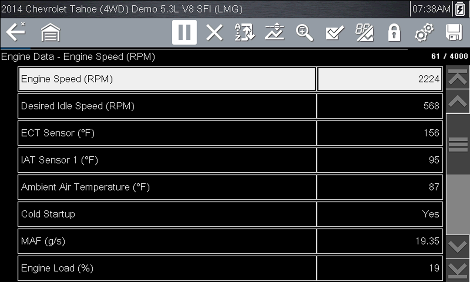
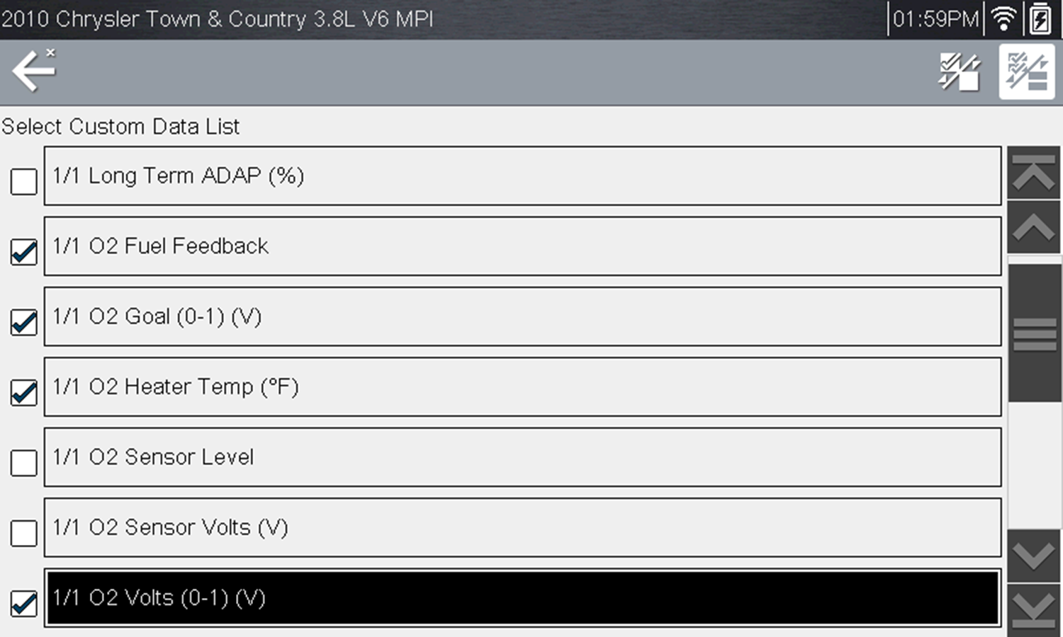
This describes typical instructions, and may not be applicable to all tools. Minimizing the number of PIDS displayed allows you to focus on any suspicious or symptom‑specific data parameters and results in a faster data refresh rate. You can add or remove most PIDs from the list, however certain vital PIDs may not be removed. These appear in gray at the top of the list along with a lock icon, and they cannot be selected.
The data selection screen displays and selection icons appear. Check marks to the left of the parameter description indicate which parameters are selected for display.
Data custom PID selection
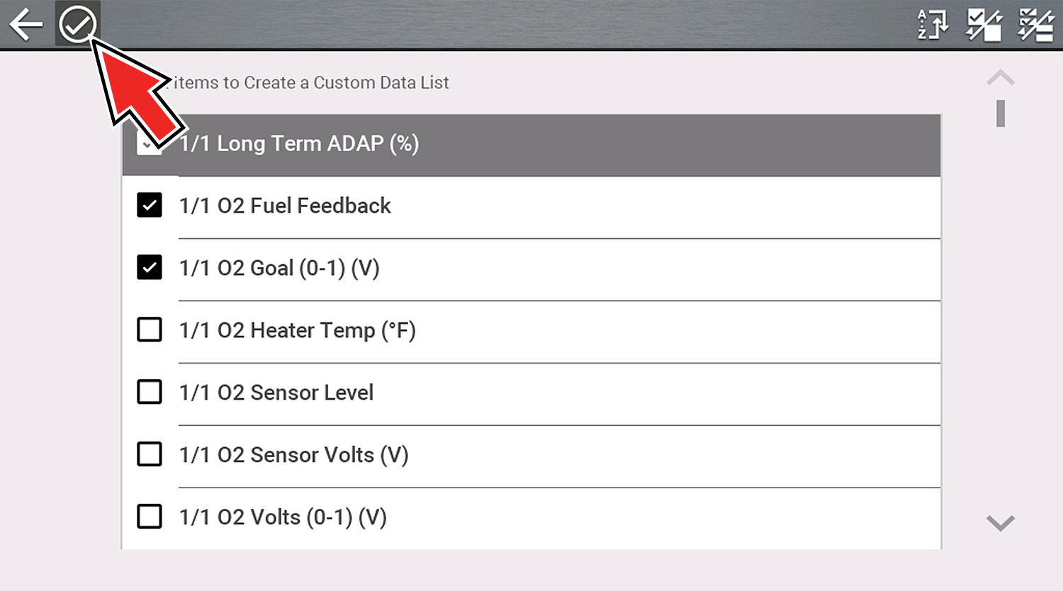
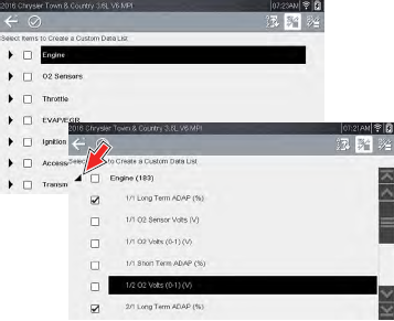
From the Custom Data list, if you select Back to display the Data Menu, your new Custom List shows as a selectable option at the top of the list. This Custom List option will only remain an option as long as you are in the Data Menu. This allows you to view other data lists and return to your Custom List, however, if you back out to the Main Menu, and then return to the Data Menu your Custom List is deleted. Cross-System Custom PID list Some vehicles may support a cross-system custom PID list, which allows you to choose multiple PIDs from across available systems to create a custom list. Selecting a cross-system custom PID list is similar to selecting a standard custom PID list, however you have the option to select PIDs from multiple lists. At the time of this publication, only select CAN integrated 2005 and later Mercedes- Benz®, Jaguar®, Chrysler®, Volkswagen® and Audi® vehicles support this feature. As future diagnostic software updates occur, additional vehicle makes and models may be included. From the data selection screen, each list item is expandable, by selecting it’s Expand icon. You can expand any item from the list and select which PIDs you want to include, and then collapse the list and choose another if desired. The check marks to the left of the parameter description indicate which parameters are selected for display.
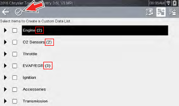
Once you have selected all the PIDs you need, select the Accept icon to view the new custom list, . The numbers indicate how many you selected for each group.
From the Custom Data list, if you select Back to display the Data Menu, your new Custom List shows as a selectable option at the top of the list. This Custom List option will only remain an option as long as you are in the Data Menu. This allows you to view other data lists and return to your Custom List, however, if you back out to the Main Menu, and then return to the Data Menu your Custom List is deleted. |
|||||||||||||||||||||||||||||||||||||||||||||||
| Scanner Operations |
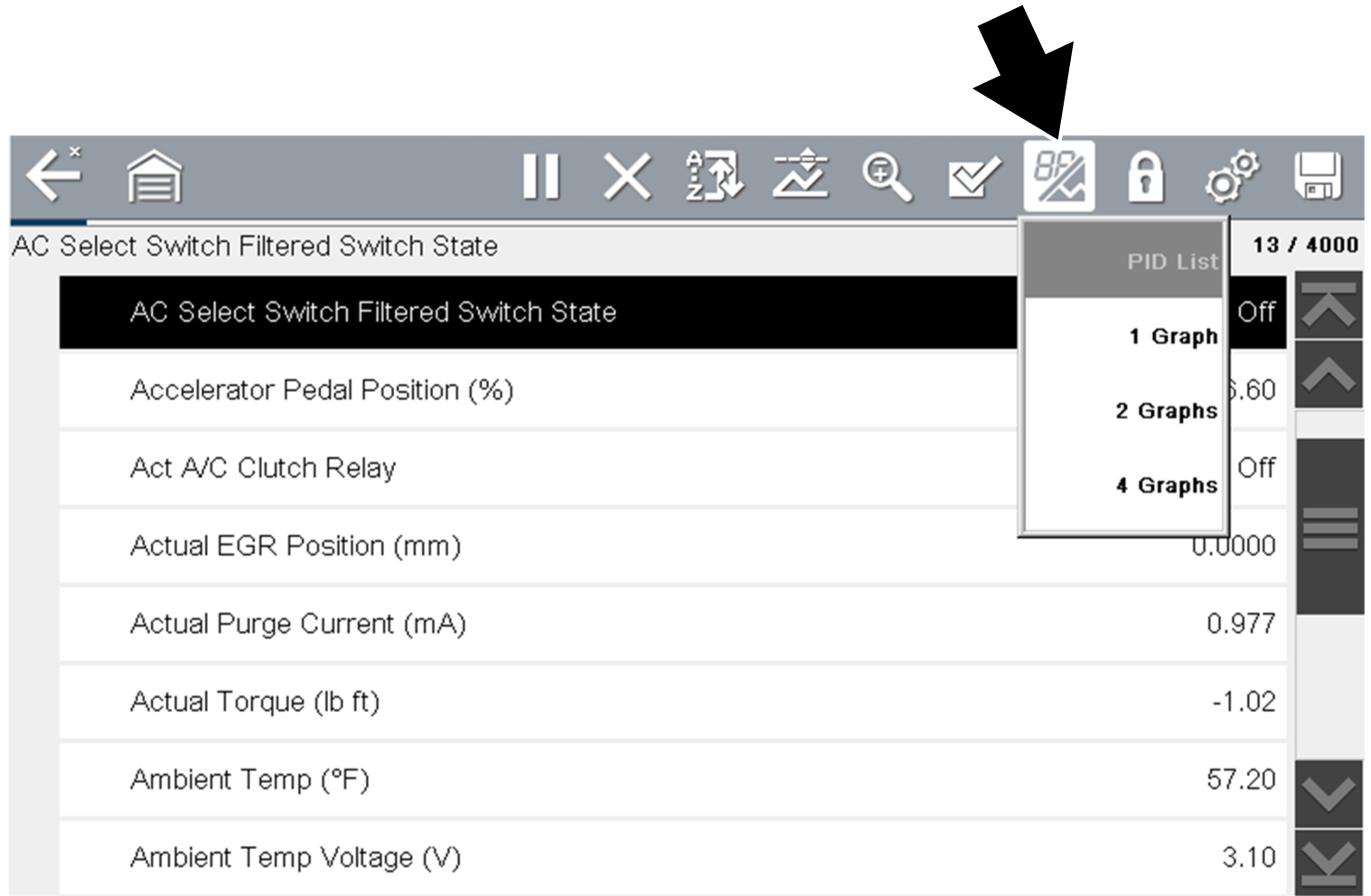
This describes typical instructions, and may not be applicable to all tools.
Selecting the View icon opens a drop-down menu of viewing options.
The PID List view is a 2-column display with the name of the parameters in the left column and their current values in the right column.
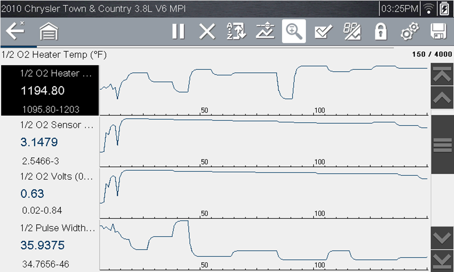
PID List view The 1, 2, and 4 Graph views divide the screen horizontally to simultaneously display data graphs for the indicated number of parameters .
Four graph view |
|||||||||||||||||||||||||||||||||||||||||||||||
| Scanner Operations |
= Home Screen > Scanner > [ID Vehicle] > [Choose System] > Functional Test Functional Tests are used to access vehicle-specific subsystem tests. Test availability varies by manufacturer, year, and model. Only the tests available/supported for the identified vehicle display in the menu. Follow all screen instructions while performing tests. How and what information is presented on the screen varies according to the type of test being performed and the vehicle being serviced. Functional tests are typically actuated by icons or controls in the upper toolbar designated to turn a component on/off or set testing times or other variables. Types of functional tests will vary:
|
|||||||||||||||||||||||||||||||||||||||||||||||
| Scanner Operations |
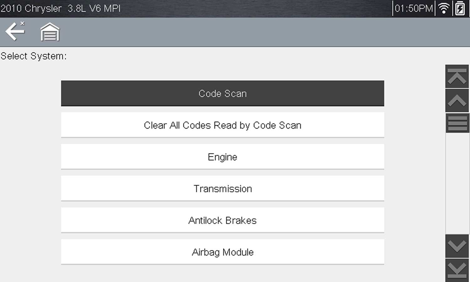
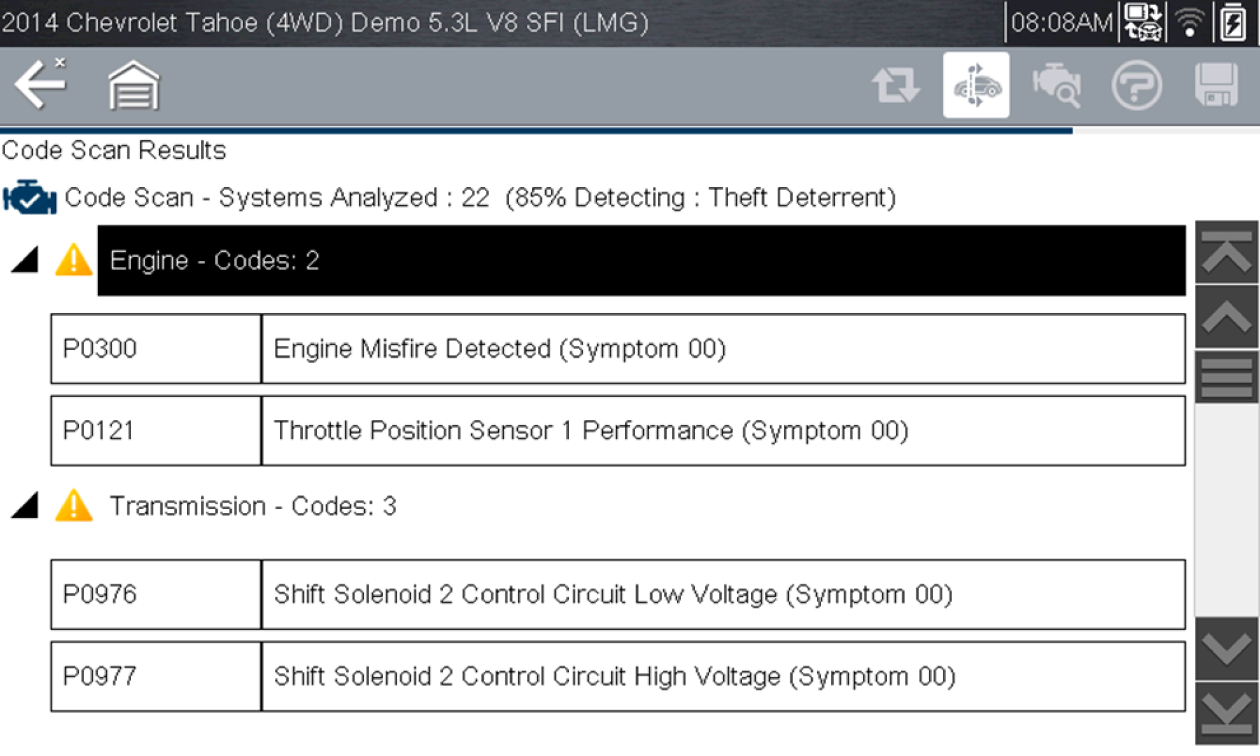
This describes typical instructions, and may not be applicable to all tools. The Code Scan function and results are dependent upon the vehicle. Not all vehicles may support this function. After you have connected and identified a vehicle with the Scanner function, Code Scan is available from the Vehicle System menu. Selecting Code Scan from the Vehicle System menu starts an active scan of vehicle control modules, and opens the Code Scan results screen.
When initially opened, a progress bar is shown at the top indicating the active scanning progress. Once completed, code results are displayed by system. The following results are displayed as the modules are scanned.
|
|||||||||||||||||||||||||||||||||||||||||||||||
| Scanner Operations |
If the vehicle is OBD-II compliant, typically 1996 and newer you can still get useful data using the OBD function, as this allows you to access “generic” OBD-II/EOBD data. The OBD-II/EOBD icon Generic OBD-II/EOBD data is limited to emission related diagnostics and allows you to access:
|
|||||||||||||||||||||||||||||||||||||||||||||||
| Scanner Operations |
Communication protocols provide a standardized way of transferring data between an ECM and a diagnostic tool. Global OBD may use the following communication protocols:
When initially attempting to establish communication with the ECM the diagnostic tool attempts to communicate trying each protocol in order to determine which one is being used. During normal operation the communication protocol is automatically detected. If automatic detection fails, communication protocol can be manually selected. To manually set the protocol, see OBD-II/EOBD > OBD Diagnose > Manual Protocol Selection Using unsupported OBD communication protocols may activate warning lights and can set network related faults. Only use the manual selection option when OBD protocol is already known. |
|||||||||||||||||||||||||||||||||||||||||||||||
| Scanner Operations |
This feature is not applicable to all tools, and requires Wi-Fi connection. Fast Track Intelligent Diagnostics provides access to code related data, information, and tests, all from one screen when viewing codes in Scanner. Quickly find TSB's, smart data PID lists, out-of-range PIDs, functional tests, Top Repairs Graph and Real Fixes, all related to the selected code. In addition, you can directly access all (not just code related) PIDs and functional tests from one place, as compared to accessing them separately through the individual system menu. In this User Manual application, see Main Menu > Diagnostic Tool Functions > Intelligent Diagnostics for details.
|
|||||||||||||||||||||||||||||||||||||||||||||||
| Scanner Operations | ||||||||||||||||||||||||||||||||||||||||||||||||
| Scope / Meter Operations |
This feature is only applicable with diagnostic tools that are equipped with a Scope/Meter (e.g. TRITON Family, MODIS Family, etc). Leads and probes are supplied with your diagnostic tool. Their recommended connection is as follows. The shielded yellow lead is used with channel 1, and is color matched with the channel 1 jack on the diagnostic tool. This lead also includes two black, right-angle common ground plugs. One plug is standard and the other is stackable. The standard ground plug should always be connected to the ground (GND) jack on the diagnostic tool.
The stackable ground plug is used for connecting additional ground leads, such as the Channel 2 or the Secondary Coil Adapter lead grounds. The stackable ground lead is internally connected to the standard ground lead, therefore it does not need to be connected to the diagnostic tool ground jack. The shielded green lead is used with channel 2, and is color matched with the channel 2 jack on the diagnostic tool. This lead also includes a black, right-angle stackable ground plug.
Insulated alligator clips and probes (pointed type) can be attached to the end of the test leads. Each alligator clip is color matched with a test lead, and the probes are available in red and black.
To purchase leads, probes and related equipment, contact your Snap-on representative and/or visit Diagnostic Tools and Accessories |
|||||||||||||||||||||||||||||||||||||||||||||||
| Scope / Meter Operations |
This An optional Low Amp Current Probe is used measure AC or DC current up to 60A. This probe includes two scales (0 to 20A) and (0 to 60A) that can be used to provide accurate and reliable non-intrusive current measurement for components such as, ignition coils, fuel injectors, fuel pumps, relays, and electric motors.
For more information, contact your Snap-on representative and/or visit Diagnostic Tools and Accessories Battery Replacement The RED LED flashes when the minimum operating voltage is approached, indicating that the battery needs to be replaced. When replacing the battery, use the 9-volt alkaline type only. Using any other type of battery in the Snap-on Low Amp Current Probe will invalidate your warranty. To replace the battery:
|
|||||||||||||||||||||||||||||||||||||||||||||||
| Scope / Meter Operations |
This feature is only applicable with diagnostic tools that are equipped with a Scope/Meter (e.g. TRITON Family, MODIS Family, etc). Different pressure transducers and adapters are available for measuring positive and negative gas and liquid pressures. Depending on the adapter, measurement capabilities range from 1 to 5000 psi and up to 29 inHg. Measurement and application capabilities vary per device.
For more information, contact your Snap-on representative and/or visit Diagnostic Tools and Accessories |
|||||||||||||||||||||||||||||||||||||||||||||||
| Scope / Meter Operations | ||||||||||||||||||||||||||||||||||||||||||||||||
| Scope / MultiMeter Operations |
This feature is only applicable with diagnostic tools that are equipped with a Scope/MultiMeter (e.g. TRITON Family, MODIS Family, etc).
The graphing multimeter(GMM) provides two channels for testing and plots a visual graphing line of the signal. The GMM uses a higher sample rate (than a DMM) to calculate signal measurements. This characteristic along with the visual graph, make the GMM ideal for finding intermittent dropouts or glitches that may not be obvious when viewing a digital value. A key advantage of the GMM is being able to capture a signal over a long time interval and then review it’s graphical history, to visually see if and when dropouts have occurred. The Lab Scope provides two channels for testing and allows you to visually see a signals waveform, which in turn allows you to see the strength and shape of the signal. The lab scope also samples signals at a high rate, which allows you to see a higher level of detail in short samples of the signal, especially in signals that change rapidly. In addition, the lab scope also provides more control over the acquisition of the signal and in how it is displayed, through the use of triggers and channel controls. All of these features allow you to analyze signals in great detail when performing component testing. To use these functions, open as shown below = Home Screen > Scope / Multimeter>(Lab Scope, Graphing Multimeter or Digital Multimeter) Connect the supplied test leads and probes as applicable using one or both channels and the ground lead. See How do I connect the meter leads to the tool? For additional information, within this User Manual application, see Main Menu > Diagnostic Tool Functions > Scope / MultiMeter. |
|||||||||||||||||||||||||||||||||||||||||||||||
| Secure Vehicle Gateways |
This feature is not available on all diagnostic tools. To protect vehicle communication networks from unauthorized access, OEM’s are implementing Security Link modules that only allow authorized users to access certain diagnostic functions using an approved diagnostic tool. Using Security Link and your Snap-on diagnostic tool, you can have the ability to communicate with most vehicles that are equipped with Security Link modules. Currently Security Link is only compatible with Fiat Chrysler Automobiles (FCA) 2018+ models. How do I get setup to use it, so I can connect to vehicles with Secure Vehicle Gateways?
For more information on how to setup these accounts and get authorized: See Security Link |
|||||||||||||||||||||||||||||||||||||||||||||||
| ShopStream Connect |
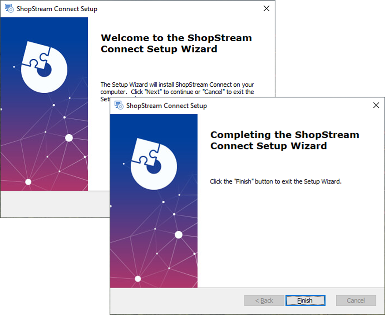
The ShopStream Connect™ (SSC) software is a free PC-based software that extends the capabilities of your diagnostic tools. Application and features will vary across diagnostic tools. View, Print, and Manage data saved from your Diagnostic tool.
Downloading and Installing Windows® 8/8.1 or 10 is required to use ShopStream Connect.
Visit your product specific market website to download the application. For the United States and Canada visit: snapon.com/diagnostics/us/SSC
For additional information, see Main Menu > Additional Resources > ShopStream Connect |
|||||||||||||||||||||||||||||||||||||||||||||||
| ShopStream Connect |
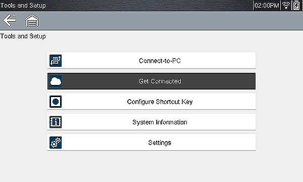
Connect-to-PC allows you to transfer saved data files on your diagnostic tool to your personal computer using a USB cable. The optional ShopStream Connect™ PC software allows you to view, print and save data files on your PC. In addition, you can download software updates from the PC to the diagnostic tool. These features provide an ideal way to manage saved data files. = Home Screen > Tools > Connect-to -PC After the confirmation message (In Connect-to-PC mode) displays:.
The diagnostic tool, displays as an external drive. If you have ShopStream Connect installed, it may open automatically, however you may also use Windows File Explorer to transfer files. Files are located in the “USERDATA” folder.
|
|||||||||||||||||||||||||||||||||||||||||||||||
| Snap-on Cloud | ||||||||||||||||||||||||||||||||||||||||||||||||
| Snap-on Cloud | ||||||||||||||||||||||||||||||||||||||||||||||||
| Snap-on Cloud |
This feature is not available on all diagnostic tools. Snap-on Cloud is a mobile-friendly cloud-based application designed specifically for technicians to store, organize and share information. Using Snap-on Cloud (ALTUSDRIVE.com) allows you to:
To access and use the Snap-on Cloud you need to first setup a Snap-on profile, see next question. |
|||||||||||||||||||||||||||||||||||||||||||||||
| Snap-on Profile |
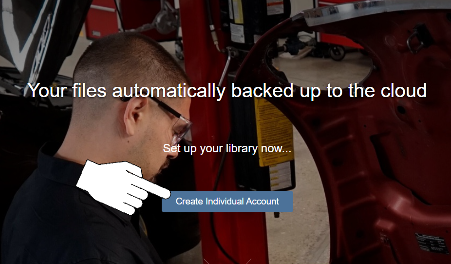
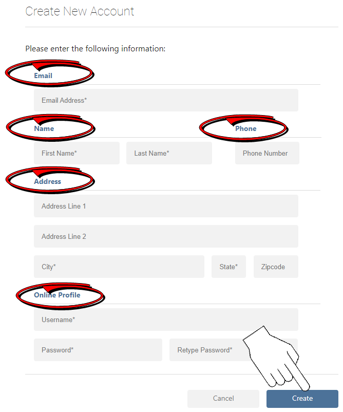
Before you can use the Snap-on Cloud or Security Link applications, you need to create a "profile" at ALTUSDRIVE.com. However, if you already have a ShopKey Pro or SureTrack account, just login using your authorized Username and Password, then proceed to step 6 below.
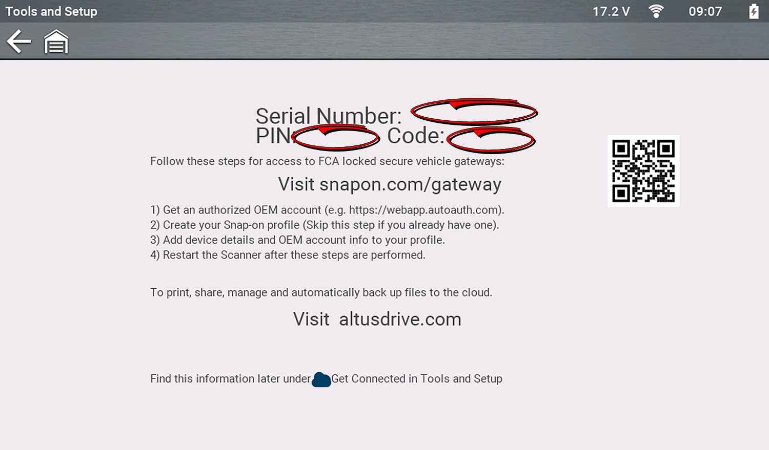
The numbers and codes needed (in the step above) are found on your diagnostic tool (see image below). The device Serial Number, PIN and Code needed to register are displayed onscreen. = Home Screen > Tools > Get Connected
|
|||||||||||||||||||||||||||||||||||||||||||||||
| Software |
Depending on your diagnostic tool, software updates/upgrades are available in the following ways (see instructions below):
Related Quick Tip Videos
Software update/upgrade using ShopStream Connect APPLICATION: TRITON-D8, APOLLO-D8, MODIS Edge, MODIS Ultra, SOLUS Edge, SOLUS Legend, SOLUS Ultra, P1000, VANTAGE Legend, VANTAGE Ultra, ETHOS Edge, ETHOS Tech, ETHOS PRO, ETHOS PLUS Windows® 8/8.1 or 10 is required to use ShopStream Connect. READ THIS BEFORE YOU START - Depending on your Wi-Fi connection and the size of the update, download times will vary. Download times can range from 15 to 120 minutes or more. It is recommended that you perform the platform software installation Monday - Friday, during business hours to ensure Customer Care representatives are available for support should you need it. Once downloaded it may take 10-15 minutes to install on the tool. If the Internet connection is interrupted or you select cancel during a download, the download is canceled. You must restart the process from the beginning. Only disable your PC anti-virus software if it blocks your ability to download an upgrade.
Visit your product specific market website to download the application. For the United States and Canada visit:
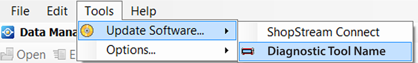
In most situations, when you connect your diagnostic tool to the PC, ShopStream Connect (SSC) will open automatically and then check for software updates/upgrades, Just follow the screen prompts to accept, download and install the software. To manually check for software updates/upgrades, from the SSC menu select Tools > Update Software, then select your diagnostic tool (e.g. APOLLO-D8, TRITON-D9, etc.).
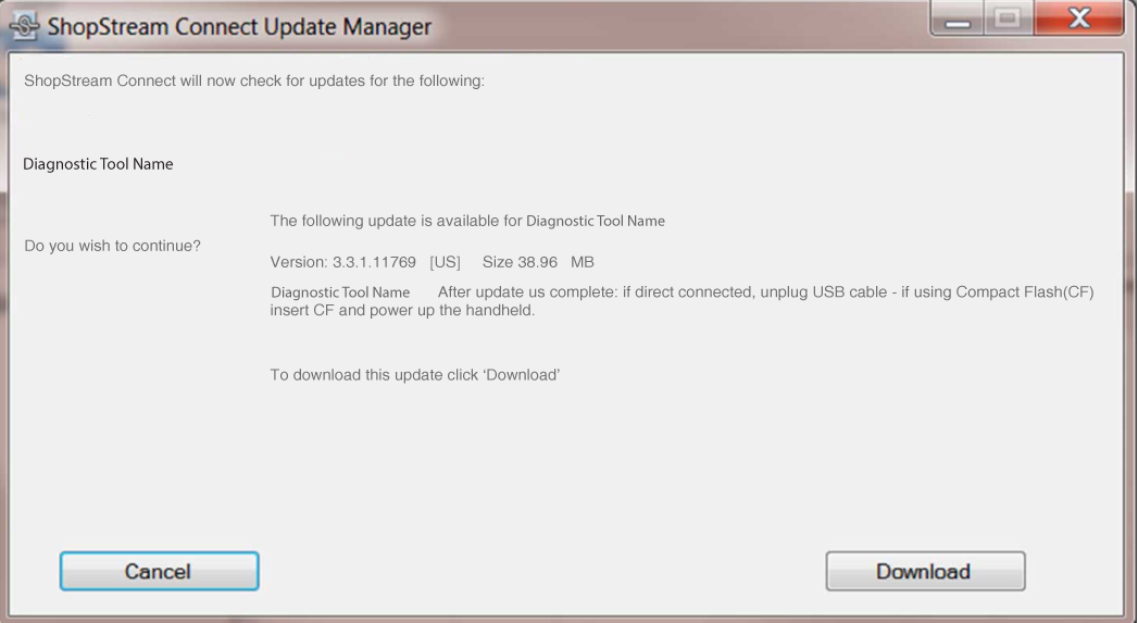
The software checks the Snap-on web server for available updates/upgrades. If service release updates are available, select Next to continue, then select Download and follow the on-screen instructions to complete the installation.
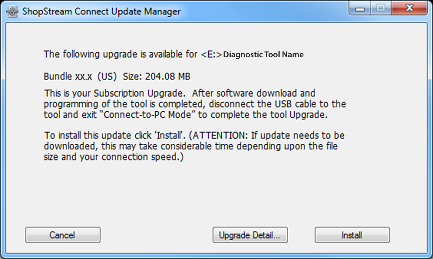
If software upgrades are available, select Next > Download > Install and follow the on-screen instructions to complete the installation, see below.
Selecting Upgrade Detail automatically connects to the Snap-on web server and opens a PDF file with information about the new upgrade. Install window
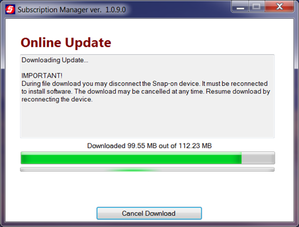
Update status window
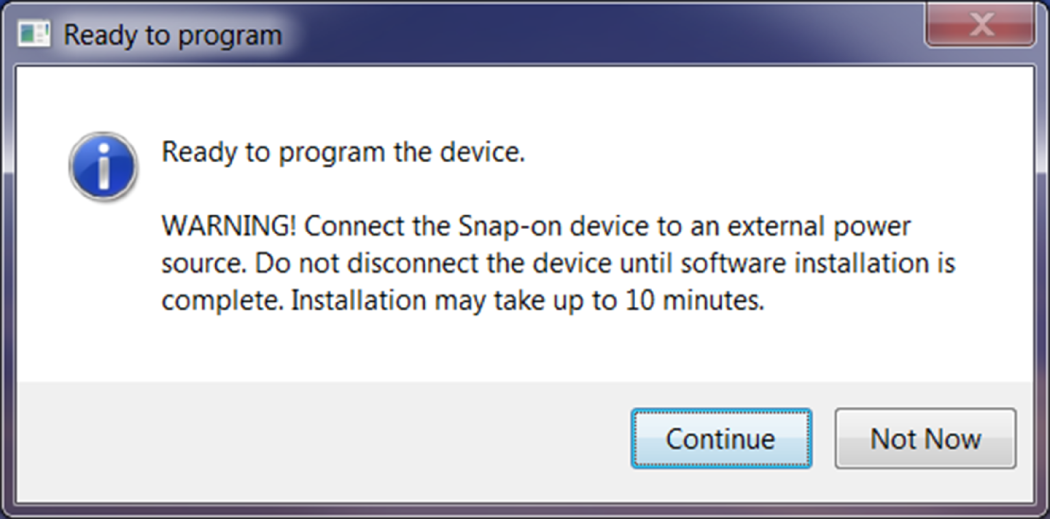
After the download is complete, the installation confirmation message is displayed. Select Continue to proceed with the software upgrade installation.
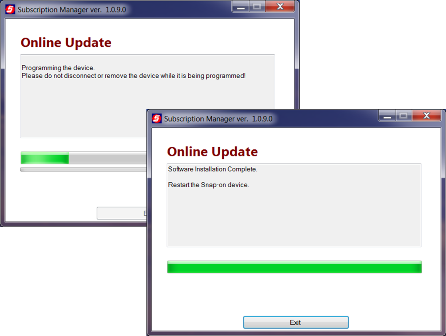
The Programming status window is displayed until programming is completed. Once programming is completed select Exit, then restart the diagnostic tool. Do not disconnect or remove the diagnostic tool during programming.
Additional SSC Software Update/Upgrade esources: https://www.snapon.com/EN/US/Diagnostics/SSC https://www.snapon.com/Diagnostics/US/KB/DQT-GG-ShopStream-Connect-Software-Updates.htm |
|||||||||||||||||||||||||||||||||||||||||||||||
| Software |
Software license agreements are integrated into the software and are "accepted" when the tool is initially activated and whenever a new software upgrade is installed. Use of Software is governed by the terms and conditions of the End User License Agreement. The diagnostic tool should not be initially operated until the End User License Agreement is read. Use of the device acknowledges your acceptance of the End User License Agreement. The Snap-on Incorporated Software End User License Agreement may be provided with the diagnostic tool, and is available at: https://eula.snapon.com/diagnostics For customer and end-user access and convenience, Snap-on is providing the End User License Agreements (link above) applicable to the Snap-on Diagnostics software and platforms. These agreements or an earlier one you agreed to was either provided as hard copy or resident within the diagnostics platform software. |
|||||||||||||||||||||||||||||||||||||||||||||||
| Software |
The diagnostic tool software version is displayed on the System Information screen: = Home Screen > Tools > System Information |
|||||||||||||||||||||||||||||||||||||||||||||||
| Software | ||||||||||||||||||||||||||||||||||||||||||||||||
| SureTrack |
This feature is not applicable to all tools. If you have purchased a new diagnostic tool, you will need to create a SureTrack account before you can access SureTrack. SeeSureTrack |
|||||||||||||||||||||||||||||||||||||||||||||||
| SureTrack |
This feature is not applicable to all tools. If you have recently purchased a software upgrade, you will need to reactivate your account to access SureTrack. SeeSureTrack |
|||||||||||||||||||||||||||||||||||||||||||||||
| SureTrack |
This feature is not applicable to all tools. SeeSureTrack SureTrack is an evolving database of "real-world" automotive repair knowledge based on expert knowledge and millions of actual repair orders. It was designed to help you improve automotive diagnostic accuracy and reduce repair times. SureTrack information (Real Fixes/Tips, Top Repairs graphs) is provided in two ways, by WiFi in the integrated Scanner function on your diagnostic tool, and online via the SureTrack Community application. SureTrack is not available for motorcycles. |
|||||||||||||||||||||||||||||||||||||||||||||||
| Troubleshooting |
Check the power source. |
|||||||||||||||||||||||||||||||||||||||||||||||
| Troubleshooting |
In situations where the display is frozen and is not responding to touch screen actions or control buttons, it may be necessary to perform an emergency shutdown. It is not recommended to do this during active vehicle communication, try to exit vehicle communication before shutting down. To force an emergency shutdown, press and hold the Power button for five seconds until the diagnostic tool turns off. then try and reboot the tool and resume operations. If you are still experiencing erratic or abnormal operation, try connecting to a different vehicle and/or using a known good data cable or scan module (as applicable). If you are still experiencing difficulties, contact customer support Phone
|
|||||||||||||||||||||||||||||||||||||||||||||||
| Vehicle History |
= Home Screen > Previous Vehicles and Data > Vehicle History The diagnostic tool stores the identification of the last twenty-five vehicles tested, so there is no need to go through the complete vehicle identification sequence when performing a retest after repairs have been made. The oldest vehicle record is deleted when a new vehicle is identified once there are twenty-five vehicles on file. Select the vehicle from the list and follow the prompts to re-activate it.
|
|||||||||||||||||||||||||||||||||||||||||||||||
| Vehicle Specific Information |
This feature is not applicable to all tools.
= Home Screen > Quick Lookups > Oil Specs and Resets This application requires Wi-Fi connection and is not available on all diagnostic tools. |
|||||||||||||||||||||||||||||||||||||||||||||||
| Vehicle Specific Information |
This feature is not applicable to all tools.
= Home Screen > Quick Lookups > Tire and Wheel Service This application requires Wi-Fi connection and is not available on all diagnostic tools. |
|||||||||||||||||||||||||||||||||||||||||||||||
| Vehicle Specific Information |
ShopKey Pro is a specialized service that provides OEM repair information, procedures, TSBs, wiring diagrams, and much more. In addition it has shop management capabilities like estimating, ordering and more. Visit ShopKey Pro to learn more. |
|||||||||||||||||||||||||||||||||||||||||||||||
| Vehicle Specific Information |
|
|||||||||||||||||||||||||||||||||||||||||||||||
| Vehicle Specific Information |
Visit ShopKey Pro to learn more. |
|||||||||||||||||||||||||||||||||||||||||||||||
| Videos |
Videos are provided for most tools at:
|
|||||||||||||||||||||||||||||||||||||||||||||||
| Warranty |
Use our online registration form to create and submit your contact information. Registering your diagnostic tool allows you to obtain warranty assistance and receive periodic messages from Snap-on about current products, features and promotions. Register online (United States) : https://registration.snapon.com/products/DiagProductRegistration.aspx Register online (Canada) : snapon.com/productregistration Also see Warranty Information |
|||||||||||||||||||||||||||||||||||||||||||||||
| Wi-Fi |
The Wi-Fi feature is not applicable to all tools. The diagnostic tool Wi-Fi connection is only for the purpose of connecting to the Snap-on Diagnostics Information service in order to use features like Fast Track Intelligent Diagnostics, Snap-on Cloud, The Wi-Fi connection does not provide access to the conventional Internet or any other services. It is recommended to keep Wi-Fi on and connected at all times. |
|||||||||||||||||||||||||||||||||||||||||||||||
| Wi-Fi |
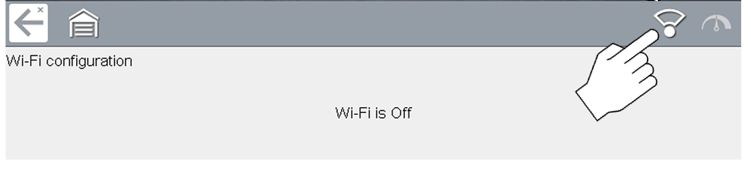
This feature is not applicable to all tools. This describes typical connection instructions. See Wi-Fi Connection / Troubleshooting = Home Screen > Tools > Settings > Configure Wi-Fi
A password is required when choosing a secured (protected) network. Networks with a proxy, challenge page, or that require the user to accept terms of usage are not supported. Wi-Fi performance varies depending on your wireless network equipment and ISP. Enter the required password and press Next, or select Connect to continue.
|
|||||||||||||||||||||||||||||||||||||||||||||||
| Wi-Fi |
This feature is not applicable to all tools. ONLY the following tools support 2.4GHz Wi-Fi: APOLLO D8 ETHOS Edge MODIS Edge MODIS Ultra P1000 SOLUS Edge SOLUS Legend TRITON D8. Router Information Router compatibility and setup are important factors to check when trying to determine connectivity problems. Although we have tested this device at the factory to verify connectivity, we cannot guaranty its connectivity with your specific equipment. There may be some situations that require your time for router connection troubleshooting and/or additional consultation and equipment. Snap-on Incorporated is not responsible for any costs incurred for any additional equipment, labor or consultation charges or any other costs that may result from correcting non-connectivity issues with this device. Routers using WEP encryption are not supported and should not be used. Verify the following router settings BEFORE you begin troubleshooting a non-connectivity or “No Connection” problem. After each check, make any corrections as necessary then retest for connectivity. Contact your IT administrator or ISP for assistance.
Routers using WEP encryption are not supported and should not be used.
Troubleshooting Chart
See Wi-Fi for additional information. |
|||||||||||||||||||||||||||||||||||||||||||||||
| Not Finding an Answer to My Question |
In the United States and Canada: Website
Phone
Online Contact Form
|
|||||||||||||||||||||||||||||||||||||||||||||||
| Customer Support |
In the United States and Canada: Website
Phone
Online Contact Form
|
|||||||||||||||||||||||||||||||||||||||||||||||


 is located on the Home screen.
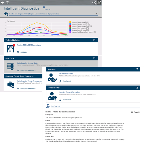


 The
The 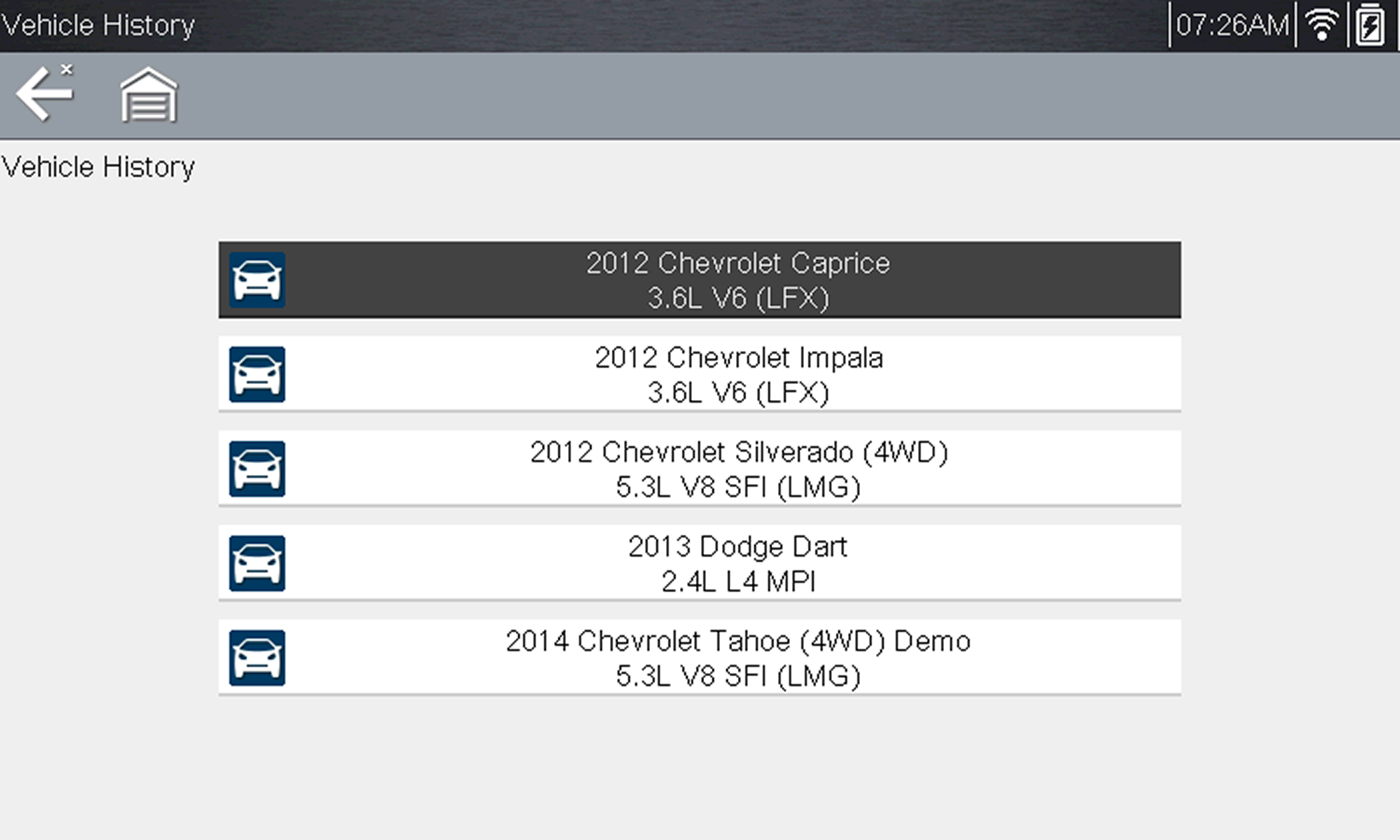
 The Quick Lookups feature provides access to vehicle manufacturer, Engine Oil Specifications, Oil Service Reset Information
 indicating Wi-Fi is on.