Vehicle Communication Systems & Related Topics
By Damien Coleman, Product Manager / EBI Specialist.
Local Interconnection (LIN) Bus is a low speed cost effective alternative to CAN bus. LIN gets its name from being a ‘local’ sub-system. Data Transfer speeds can be up to 20 kBits/second. It is designed for sensor/actuator level.
Data Transfer Speed
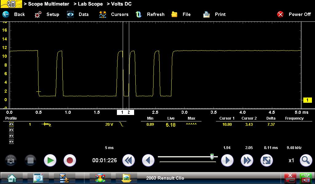
The waveform below shows a typical LIN trace, the time for the transmission of one bit is 0.11ms, this equates to a data transfer speed of 9480 bits per second (approximately 10 kBits/second).
Network Topology
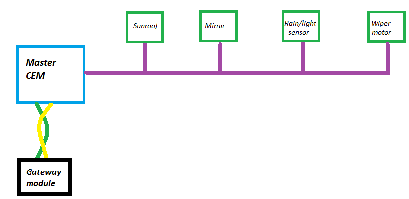
The bus can contain up to 16 modules or subscribers. One master (module) and fifteen slaves (intelligent components). LIN is a linear bus topology, with communication over a single wire.
The illustration below shows a basic network topology:
The Central Electronics Module (CEM) is the master module and communicates with the gateway module using Controller Area Network (CAN) bus. Each of the LIN components is a sensor or actuator, with the ability to transmit and receive a LIN message. The master module is responsible for controlling the timing of the message data packet.
The image above shows a CEM and front wiper motor. The purple wire is the LIN bus wire and is used to control the speed and intermittent delay for the wipers.
Message Structure
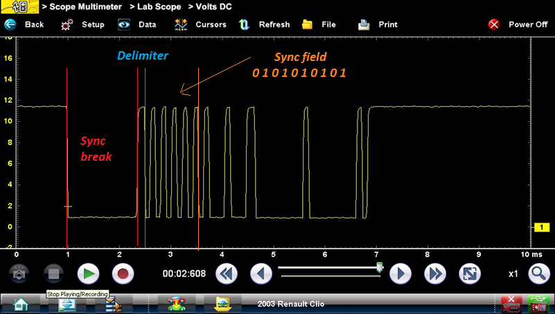
The waveform below shows a LIN message with the defined message structure. The “Sync Break” is used to signal the beginning of the message. The delimiter indicates the completion of the Sync break and serves to show the LIN wire isn’t shorted to ground. The Sync field is to ensure the timing of the message is set prior to the data field being transmitted. This is not required for CAN bus as each module on the network has its own time clock for message timing.
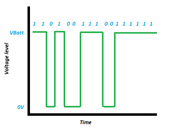
The message is transmitted by manipulating the voltage on the LIN data circuit.
1 = Recessive bit.
2 = Dominant bit.
For accuracy of data transfer the following conditions must be met:
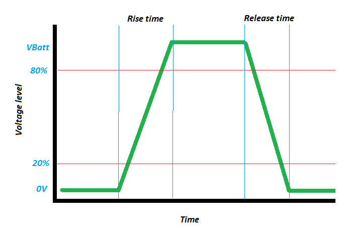
For a recessive bit, the LIN voltage must be greater than 80% of the battery voltage.
For a dominant bit, the LIN voltage must be less than 20% of the battery voltage.
The slew rate or transition time between a high bit and a low bit is critical too for data transfer.
Vehicle charging systems
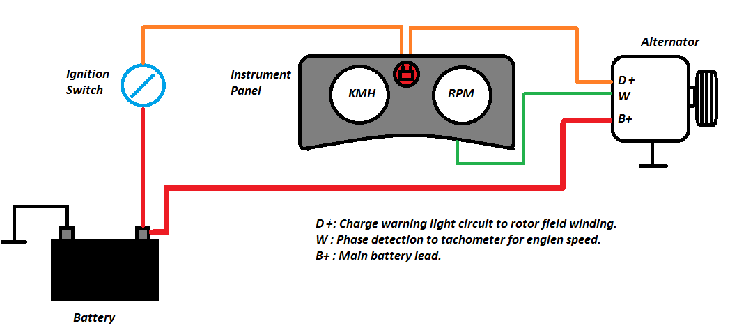
One particular system which has utilised LIN bus communication is the vehicle charging system. The diagram below shows a conventional charging system layout fitted to an older vehicle.
The D+ terminal is used as an exciter current for the rotor field winding. The rotor field winding is wired in series with the charge warning light. The W terminal was used for measuring engine speed by tapping off a stator phase.
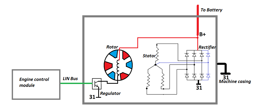
A layout of a modern system using LIN bus is shown below:
The internals of the alternator are fundamentally the same:
| ● | Rotor poles. |
| ● | Rotor field winding. |
| ● | Stator. |
| ● | Rectifier (used to convert Alternating Current to Direct Current). |
The exception being the Engine Control Module uses the LIN bus to control a transistor which varies the current flow through the rotor field winding to control the output voltage of the alternator.
Part 2 of this article will address CAN Bus communication networks.
By Damien Coleman, Product Manager / EBI Specialist.
Introduction:
Controller Area Network (CAN) is a data transfer network designed to allow many nodes (modules) communicate using a standard structure and format. This has the benefit of reducing vehicle wiring and allowing additional vehicle options to be added or removed easily. Troubleshooting such a complex system is reasonably straightforward once the technician has a basic understanding of the network and how data is transferred. This article will provide the technician with the necessary tools to successfully validate a CAN bus signal and help to identify faults where present.
Basic block diagram of a typical CAN Network.
Characteristics of a high speed CAN network (Class-C)
Multiple modules are connected to the bus in parallel. The data transfer rate is 500K bits/sec for high speed CAN. That’s 500,000 pieces of data or information per second!! The signal is broadcast over two communication wires to ensure signal integrity is maintained, these wires are twisted together and are referred to as CAN High and CAN Low.
To ensure messages of the highest priority are transmitted first, an arbitration field is part of the message structure. To ensure optimum signal quality, two fixed value resistors are connected to the bus to condition the signal. These are referred to as terminating resistors.
All these characteristics will be described in greater detail below.
Signal Generation
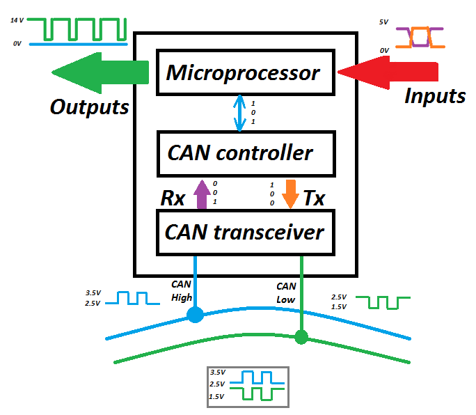
Each module on the network has a CAN controller and a CAN transceiver on the CAN chip. A transceiver has the ability to both transmit and receive data. The CAN controller converts data (binary) sent from the microprocessor and sends it to the CAN transceiver. The CAN transceiver converts the binary data into a voltage range and this is the signal voltage observed on the network.
Note: Inputs and outputs to a module are still analogue. A component such as a throttle motor will still require supplies, grounds and feedback signals as with a non-CAN vehicle.
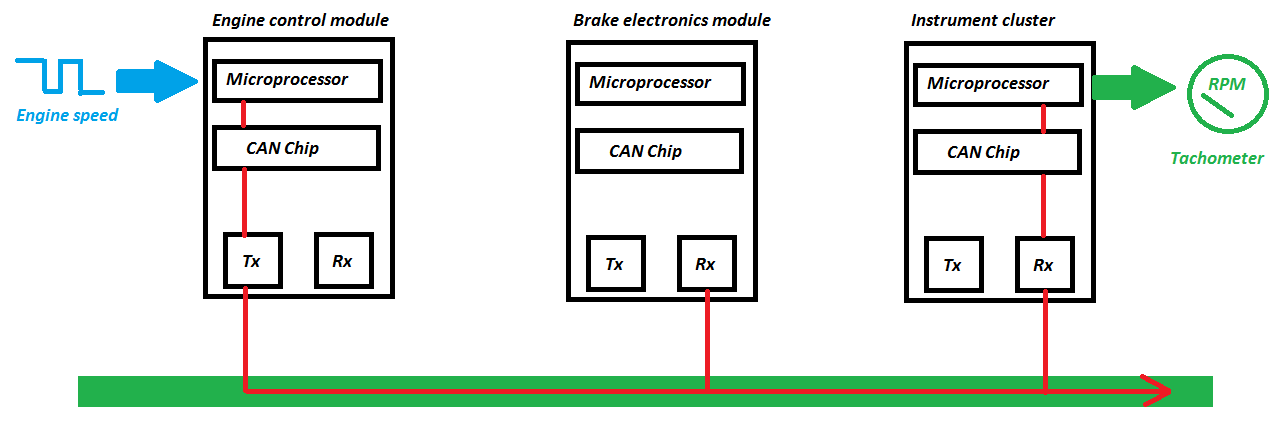
The diagram below illustrates how a message received by the engine control module is processed and transmitted on the network for other modules. In this example the engine speed input from the crankshaft position sensor to the engine ECM is also required by the Instrument cluster for the tachometer.
CAN Bus voltage levels
The table below shows the expected voltage for both recessive and dominant states on the CAN High and CAN Low wires.
|
State |
CAN High voltage |
CAN Low voltage |
Bit type |
|---|---|---|---|
|
Recessive |
2.5 volts |
2.5 volts |
1 |
|
Dominant |
3.5 volts |
1.5 volts |
0 |
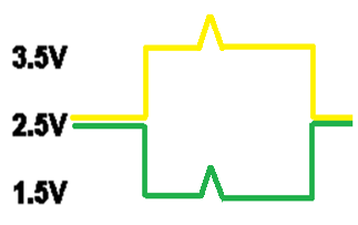
Using an oscilloscope the following voltage levels can be observed when connected to a network.
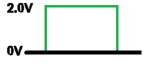
As mentioned previously both CAN high and CAN low are twisted together to reduce external interference. The diagram below shows the differential voltage between CAN high and CAN Low during data transfer.
With a recessive bit, both CAN high and CAN low voltage levels are at 2.5V so the differential voltage is 0 volts. When a dominant bit is transmitted, CAN high rises to 3.5V whereas CAN low drops to 1.5V. This is a differential voltage of 2 Volts.
In the event of a transient condition occurring, such as an external voltage spike both CAN high and CAN low will be similarly affected. So the differential voltage will remain at 2 volts, this protects the integrity of the message.
CAN bus waveform analysis
The waveform below shows both the signal when CAN high and CAN low are tested with respect to ground and the differential voltage between CAN high and Can low. Example shown from a Volvo XC – 90.
| ● | Both traces mirror each other. |
| ● | Clean without glitches or spikes. |
| ● | Correct voltage. |
| ● | Correct differential voltage. |
A technician may observe an increased voltage on a trace at the end of a message. This is the End of Frame bit and is not a cause for concern.
Signal reflection protection
Due to the high data transfer rate a means to dampen signal reflections is required. To achieve this manufacturers use two 120 Ohm resistors in parallel. Although some vehicle applications have the resistors located externally in the wiring loom, most locate the resistors in two separate modules, as shown below.
With both resistors equal in resistance and wired in parallel, the total circuit resistance is halved.
Resistance in Parallel = 

Message arbitration
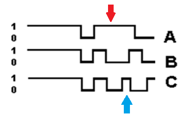
With CAN bus it must be noted that the message carries the priority, not the module ID. A message with the lowest numerical identifier, most dominant bits (0), can transmit message. All modules listen until the bus is idle again before transmitting. See the example below;
| ● | Module A loses the chance to send out its message first (Red arrow). |
| ● | Module C loses the chance to send out its message second (Blue arrow). |
| ● | Module B wins arbitration. |
Case Study – Opel Astra
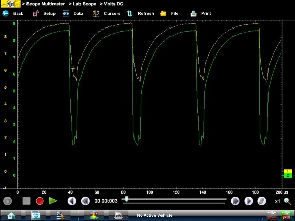
This vehicle wouldn’t start, as terminal 50 on the starter motor solenoid was not receiving current when the ignition key was turned to the start position. Also there was no communication with the Engine Management control module, Instrument cluster, Anti-Lock Brake Control module or Steering Column Integration module (CIM) using a scan tool. These modules are on the high speed CAN bus. The vehicle had a flat battery and a technician attempted to start the vehicle unsuccessfully.
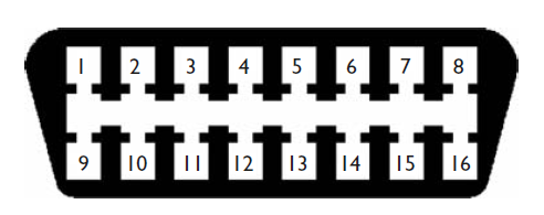
An oscilloscope was connected to pin 6 and pin 14 of the vehicle Data Link Connector (DLC) to access the high speed network.
Pin assignment:
| ● | Pin 4: Chassis ground. |
| ● | Pin 5: Signal ground. |
| ● | Pin 6: CAN High (ISO 15765). |
| ● | Pin 14: CAN Low (ISO 15765). |
| ● | Pin 16: Constant supply (+12 volts). |
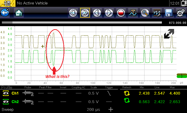
The following waveform was captured:
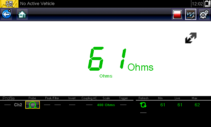
Testing the resistance of the network showed a short circuit:
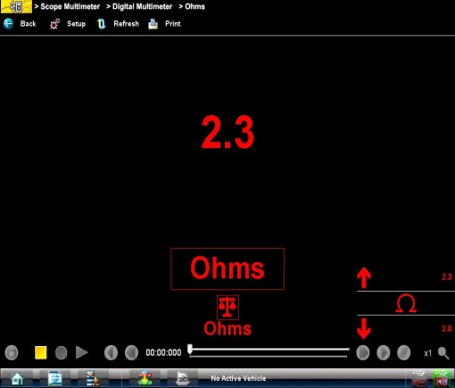
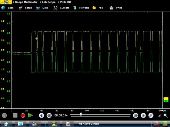
As the issue was most likely as a result of a damaged electronic control module each module on the high speed network was disconnected in turn until the network signal returned to the waveform expected. When the Anti-Lock Brake module was disconnected the oscilloscope displayed the following waveform:
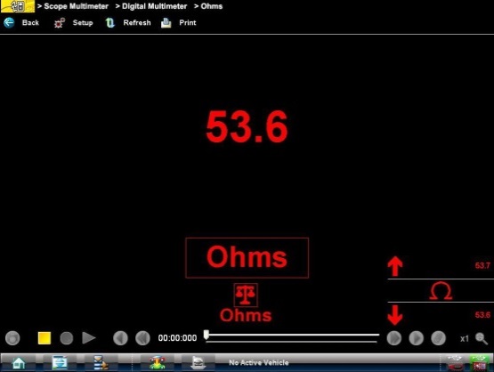
The vehicle now started and the scan tool was capable of communicating with the Engine Control Module, Instrument cluster and the CIM. The network resistance also returned to specification:
Basic systems controlled using CAN bus
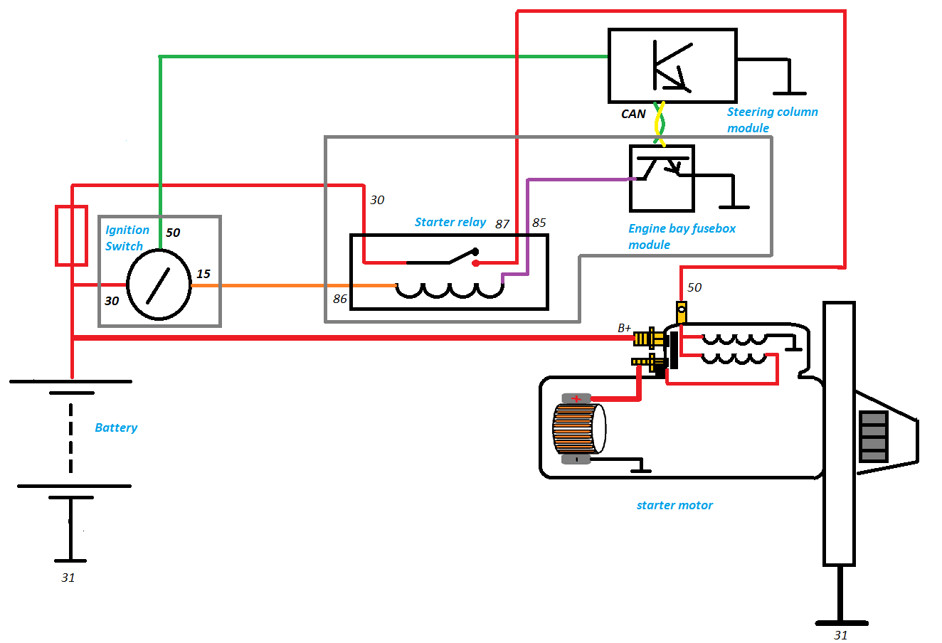
The diagram below illustrated how a basic system such as the starter motor has changed since CAN bus technology has been implemented on vehicles. The start signal from the ignition switch is sent to the Steering Column Module, once processed it is converted to a CAN message and transmitted on the CAN network. The Engine Bay Fusebox uses this message to control the starter motor relay by grounding terminal 85 of the relay winding. This results in the relay contacts closing and supplying current to terminal 50 of the starter motor solenoid.
It can be seen that the internal electrical circuit of the starter motor remains unchanged.
Pin assignment:
| ● | 30 – Constant Live. |
| ● | 31 – Ground. |
| ● | 15 – Ignition on Live. |
| ● | 50 – Starter motor solenoid control. |
| ● | 86 – Starter motor relay winding supply. |
| ● | 85 – Starter motor relay winding ground control. |
| ● | 87 – Starter motor relay contacts output. |
Gateway Module
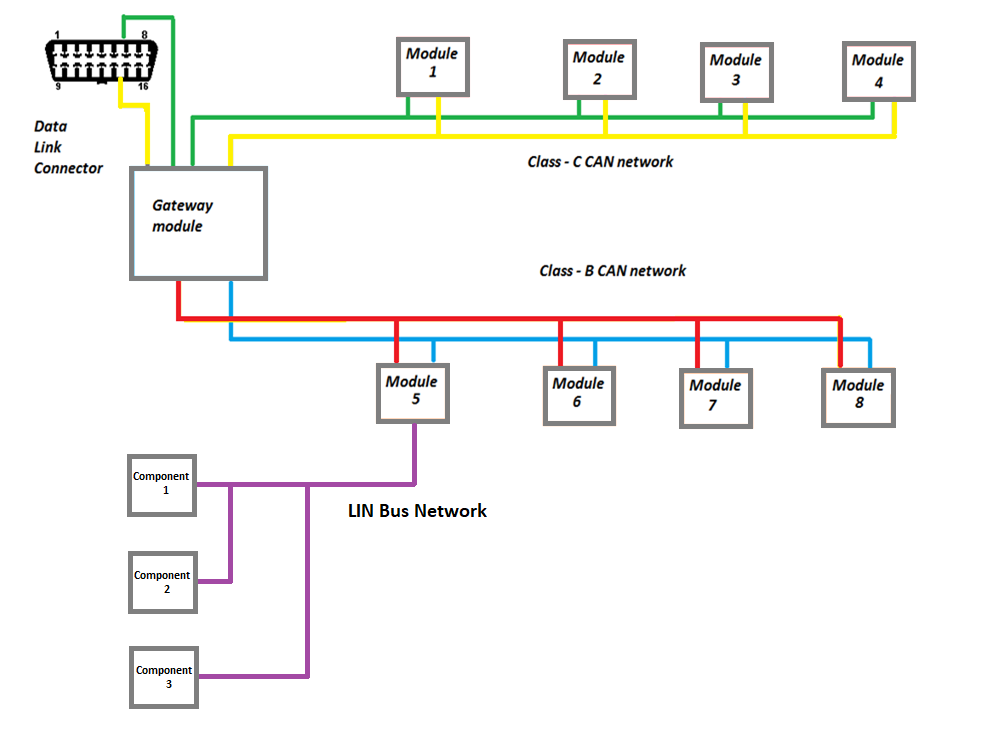
A Gateway module is used to allow modules on different networks with different data transfer speeds to communicate. The Gateway is the link between multiple networks. The module can be a separate module or part of another module such as an instrument cluster module.
The example above shows the high speed Class C CAN network (500 kBits/second), the comfort Class B CAN network (250 kBits/second) and the Lin Bus local network (10 kBits/second) all capable of communicating via the gateway module.
By Damien Coleman, Product Manager / EBI Specialist.
Introduction
In recent years to meet the demands of Drive by wire systems as well as the addition of Advanced Driver Assistance Systems (ADAS), vehicle manufacturers in association with electronic component manufacturer’s investigated possible solutions for high speed data transfer. In the previous article we looked at CAN (Controller Area Network) Bus communication, however with safety critical drive by wire systems a higher transfer data rate and improved error detection is required.
Vehicle manufacturers, Volkswagen, BMW, Daimler and General Motors became core members of the FlexRay consortium.
Physical Layer
FlexRay is similar to CAN Bus as the data is transmitted over two twisted wires, which act to reduce the effects of external interference on the differential voltage between both wires. Data transfer speeds can be up to 10 times faster than CAN bus, operating at speeds up to 1 Mbits per second. Although the normal data transfer speed for CAN is 500 kbits per second, it has the capability to transmit at speeds of 1 Mbits per second.
FlexRay can support network redundancy, or dual channels, this ensures greater fault tolerance as well as increased bandwidth for additional data transfer. However this additional network is rarely implemented.
Signal Conditioning
To match the impedance of the network cabling, a terminating resistance of 90 to 110 Ω within the modules at either end of the network is required. This ensures signal reflections are reduced, which is an issue with such high data transfer speeds.
Bus Access
CAN Bus messages are subject to arbitration to ensure messages of higher priority have access to the network first, FlexRay supports both Event triggered messaging and Deterministic messaging which allows for high data rates and guarantees message delivery when required. Each node or module has a predetermined time slot to transmit its data. This is referred to as Time Division Multiple Access or TDMA.
For sporadic messaging (event driven) TDMA is not optimal so Flexible Time Division Multiple Access or FTDMA is used.
FlexRay Voltages
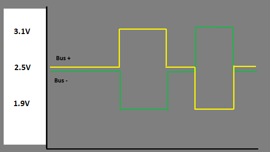
FlexRay bus voltage is similar to CAN Bus. With the bus idle or in a recessive state, the voltage present on both wires, Bus (+) and Bus (-), is 2.5 volts.
Approximate voltage levels:
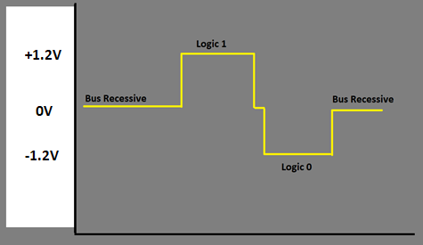
When a logic bit of 1 is required the Bus (+) voltage increases to 3.1 volts and the Bus (-) voltage reduces to 1.9V. This creates a differential voltage of +1.2 volts.
When a logic bit of 0 is required the Bus (+) voltage reduces to 1.9 volts and the Bus (-) voltage increases to 3.1 volts. This creates a differential voltage of -1.2 volts.
Two Channel Network Voltage
Differential voltage
BMW X5 Vertical Dynamics Control Module
The E70 BMW X5 was the first production vehicle to have a FlexRay network fitted. It is implemented for the Vertical Dynamics Control module, which controls the suspension height for each individual suspension strut.
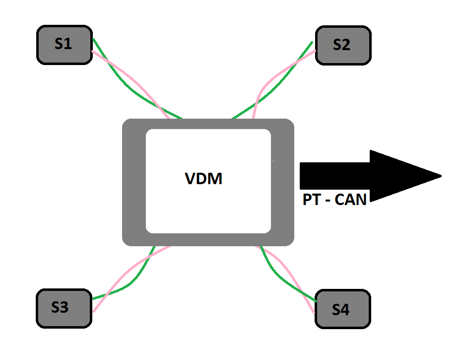
The network is configured in a Star bus. This ensures the system can still operate if a satellite unit fails. It is also an advantageous setup when long lengths of wiring are required, as normal electrical interference will only affect one leg of the network due to this configuration. A satellite unit is located in each corner of the vehicle.
| ● | VDM – Vehicle Dynamics Control Module. |
| ● | S1 – Satellite sensor Left Front. |
| ● | S2 – Satellite sensor Right Front. |
| ● | S3 – Satellite sensor Left Rear. |
| ● | S4 – Satellite sensor Right Rear. |
| ● | PT CAN – Powertrain CAN Bus. |
A terminating resistor of 90 – 110 Ohms is fitted in each of the satellite units.
Waveforms
Due to the incredibly high data transfer speed of FlexRay, in depth waveform analysis is difficult. However the oscilloscope can be used to validate that a signal is present on the network and to test for an open or short with in the circuit.
The waveform below shows a trace captured from a FlexRay system. The zero lines are set up to show the transition between a Logic 1 and Logic 0 bit due to the voltage switch for Bus + and Bus-.
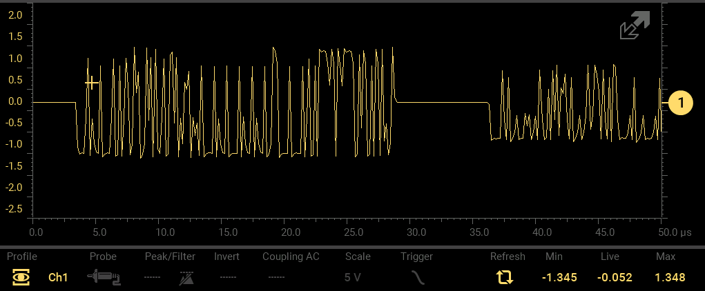
The waveform below shows the differential voltage between Bus + and Bus -. This is observed using a single channel test with channel 1 connected to Bus + and the oscilloscope scope ground connected to Bus -.
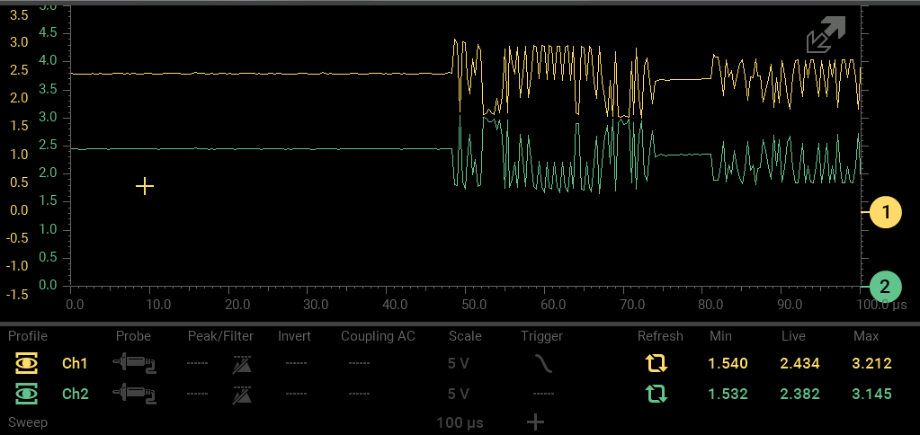
The waveform below shows Bus + and Bus – separated to show the mirror image of both traces.
A Snap-on® platform can help you to overcome the challenges and get to the root cause of the problem.
You will need to use the lab scope function, because that’s the only way to test a vehicle’s CAN network, but once you’re hooked up your tool will tell you what you need to know.
Using a Snap-on VERUS® Edge car diagnostic tool as an example, connect to a DLC break-out box using channels 6 and 14, which will be the same whatever you are working on as all CAN network vehicles terminate on pins 6 and 14 as standard. Connect the ground to pin 4 or 5.
Set both channels on your lab scope to a 10v scale to give yourself a large, clear window in which to analyse the data, then set the time base down to 100 micro-seconds.
Pause the scope to take some measurements. The squares shown on the graph illustrate when data is being transferred within the vehicle but your main interest will be in the voltages being recorded.
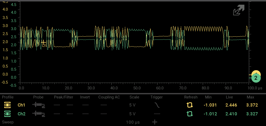
Where the yellow and green lines meet you want to see a reading of around 2.5v then when the lines separate, during data transmission, one should go up by a volt and one should drop by a volt if everything is operating correctly.
Setting the channels to a 10v scale has the added advantage of making it easier to see when there is an issue – if one of the lines drops to zero then there’s a bad ground or ground issue, while if the voltage rises outside of the expected readings then there is a power problem.
So as you can see, the lab scope option is a straightforward way to help diagnose communication on CAN network vehicles and should always be considered.
Diagnosing vehicle communication issues can be a challenge on some of the newer models in today’s market.
It can be hard to know where to start given the amount of different types of networks that these vehicles operate with.
But there are ways to get to the bottom of issues efficiently using the Guided Component Tests provided by the diagnostic software and scan tools from Snap-on.
Let’s use a 2013 BWM X5 as an example. That vehicle has a Flex Ray Bus network, which is much faster than CAN (Controller Area Network) systems.
A built-in Guided Component Test will help you to use your lab scope to check whether the vehicle is communicating as it should do.
Once you have hooked up your tool and allowed it to automatically ID your vehicle, go to Fuel Injection System in order to test the communication networks then choose Flex Ray Bus.
This will help you to run a signature test, and before you do so the system will also give you all of the information you need so that you can correctly connect all of your test leads.
When that is done, you can also see a clear picture of what the signature is supposed to look like and also some voltage ranges so that you know what to look out for.
Hit the View Meter button to show the signal coming from the vehicle and compare it to the data shown in the test.
If there were any problems, such as a short to ground or short to five-volt power, they would be shown up pretty quickly on the signal and would stand out given that Flex Ray Bus networks normally operate within the five-to-zero volt range.
This particular Guided Component Test gives you a quick and easy way to diagnose no-communication issues on modern network systems.
The Snap-on diagnostic software includes Component Test Meter coverage for hundreds of vehicles and systems across 49 manufacturers.
By Damien Coleman, Product Manager / EBI Specialist.
This 2017 Volvo XC60 with a 2 litre common rail diesel injection engine (D4204T14) had multiple electrical failures reported by the owner. These were all relating to the Body electrical system. The faults were intermittent in nature. When the issue was present the following sub-systems failed to operate:
| ● | Remote Keyless Entry. |
| ● | Instrument Panel. |
| ● | Electronic Climate Control. |
| ● | Infotainment system. |
| ● | Central Locking. |
| ● | Electric Windows. |
| ● | Power Mirrors. |
| ● | Directional Indicators. |
| ● | Power Tailgate. |
The vehicle would start and operate as expected even with the issue present. A Scan Tool was connected to the vehicle’s Data Link Connector (DLC) and numerous fault codes were stored. The following codes were found with a full system Code Scan:
Module |
Fault Code ID |
Fault Code Title |
|---|---|---|
|
Central Electronic Module |
U015500 |
Lost Communication with Driver Information Module |
|
Central Electronic Module |
U016400 |
Lost Communication with Climate Control Module |
|
Central Electronic Module |
U019900 |
Lost Communication with Driver Door Module |
|
Central Electronic Module |
U020000 |
Lost Communication with Passenger Door Module |
|
Central Electronic Module |
U001011 |
Medium Speed CAN Bus - Short to Ground |
|
Central Electronic Module |
U001088 |
Medium Speed CAN Bus – Bus Off |
|
Central Electronic Module |
U021400 |
Lost Communication with Keyless Vehicle Module |
|
Central Electronic Module |
U023000 |
Lost Communication with Power Tailgate Module |
|
Supplementary Restraint Module |
U015500 |
Lost Communication with Driver Information Module |
|
Driver Information Module |
U001088 |
Medium Speed CAN Bus – Bus off |
|
Driver Information Module |
U210000 |
Control Module Unconfigured |
|
Driver Door Module |
U001000 |
Medium Speed CAN Bus – General Fault |
|
Driver Door Module |
U014000 |
Lost Communication with Central Electronic Module |
|
Driver Door Module |
U016487 |
Lost Communication with Climate Control module |
|
Passenger Door Module |
U001000 |
Medium Speed CAN Bus – General Fault |
|
Passenger Door Module |
U014000 |
Lost Communication with Central Electronic Module |
|
Passenger Door Module |
U016487 |
Lost Communication with Climate Control module |
|
Climate Control Module |
U001088 |
Medium Speed CAN Bus – Bus off |
|
Climate Control Module |
U014000 |
Lost Communication with Central Electronic Module |
|
Infotainment Control Module
|
U001000 |
Medium Speed CAN Bus – General Fault |
|
Keyless Vehicle Module |
U001000 |
Medium Speed CAN Bus – General Fault |
|
Power Operated Tailgate |
U001000 |
Medium Speed CAN Bus – General Fault |
|
Power Operated Tailgate |
U210000 |
Control Module Unconfigured |
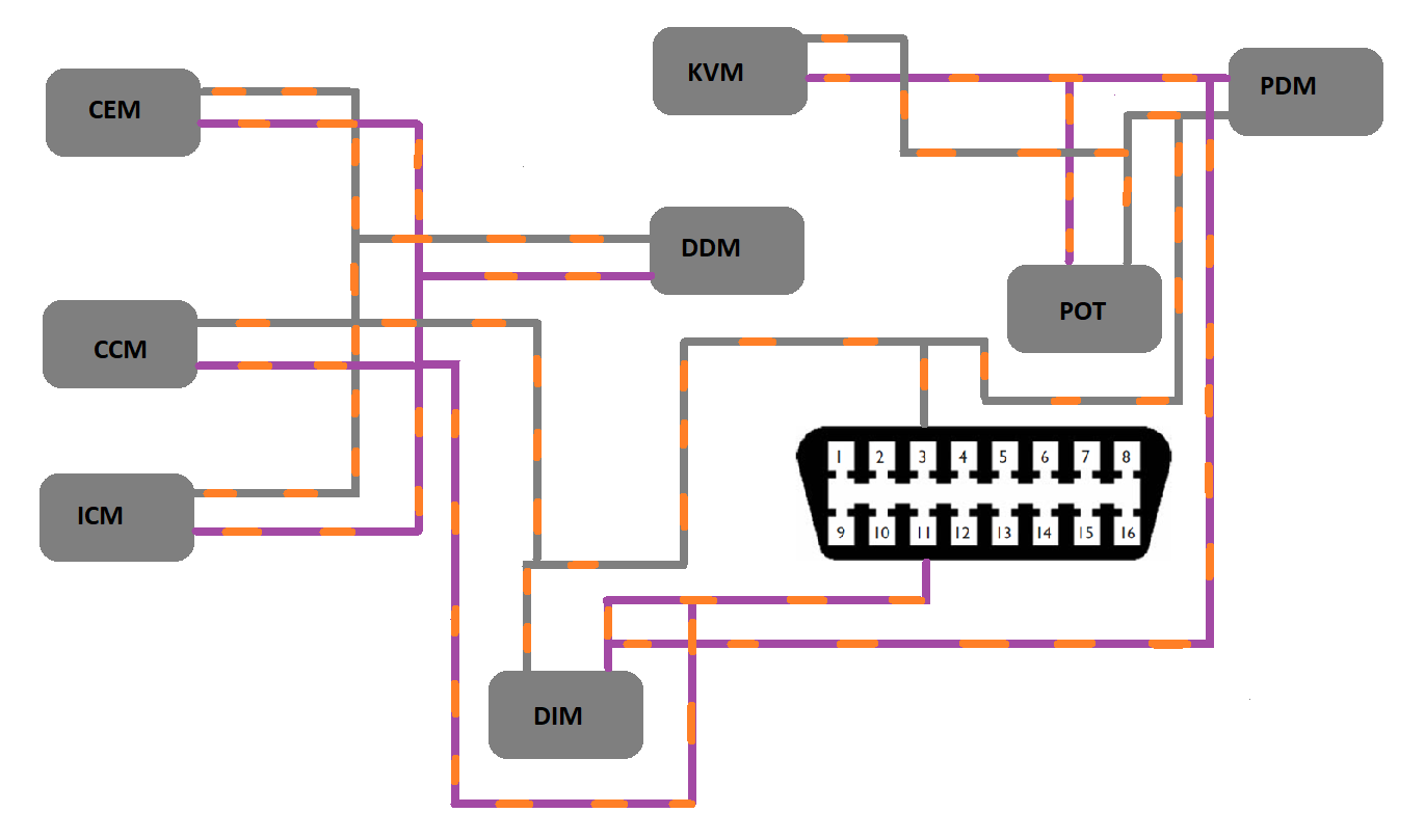
A wiring diagram was consulted to investigate the modules which communicate on the Medium Speed data bus. The diagram below is a simplified diagram showing the modules on the Mid speed network.
| ● | CEM – Central Electronic Module. |
| ● | CCM – Climate Control module. |
| ● | ICM – Infotainment Control Module. |
| ● | DIM – Driver Information module. |
| ● | DDM – Driver Door Module. |
| ● | PDM – Passenger Door Module. |
| ● | KVM – Keyless Vehicle Module. |
| ● | POT – Power Operated Tailgate. |
It can also be seen from the diagram that pin 3 and 11 at the Data Link Connector (DLC) are connected to the Medium Speed CAN Bus. This is a very convenient point to test the network. A 16 pin break-out box can be used to allow easy access to the DLC pins.
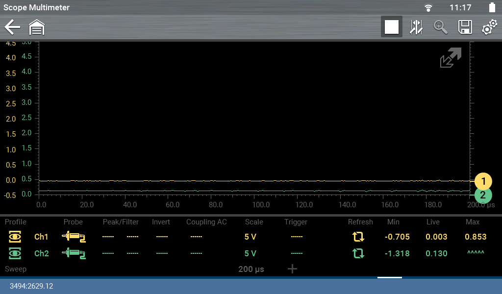
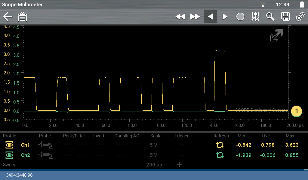
An oscilloscope was connected to the breakout box and the following waveform was observed when the faults were present.
| ● | Yellow Channel – Pin 3. |
| ● | Green Channel – Pin 11. |
It can be seen from this waveform that there is no activity on the network and the voltage is close to ground potential.
This issue can occur due to a module internally shorting the network to ground or a wiring fault creating the short circuit. One of the more common areas on a vehicle for wiring problems is the wiring loom where it enters the doors. As faults were present in both the Driver and Passenger Door Modules this was the first area to be investigated. The wiring to both the driver and passenger door was undamaged and disconnecting one door at a time did not resolve the issue.
Another common failure on modern vehicles is the instrument cluster. On this particular vehicle the cluster is relatively easy to remove and disconnect the electrical connector. No issue was found here and with the module disconnected the network did not become active.
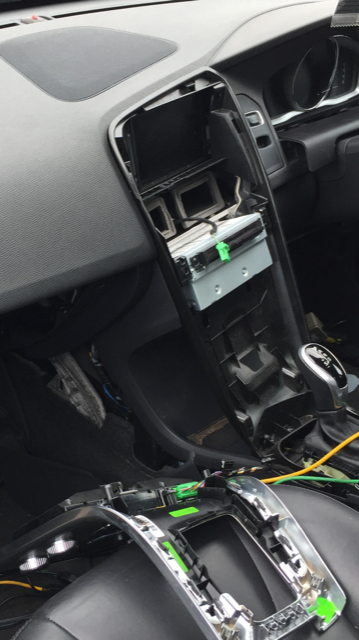
The next part of the network to be investigated was the Climate Control Module. It was noticed that the CAN signal was intermittently present while the CCM was being removed from the dash. Applying hand pressure to the dashboard resolved the issue, removing the hand from the dash resulted in the fault re-appearing. This is indicative of a wiring fault and in particular a wire(s) shorting against a vehicle ground. The CCM, glovebox, radio and various trim panels were removed to inspect the wiring.
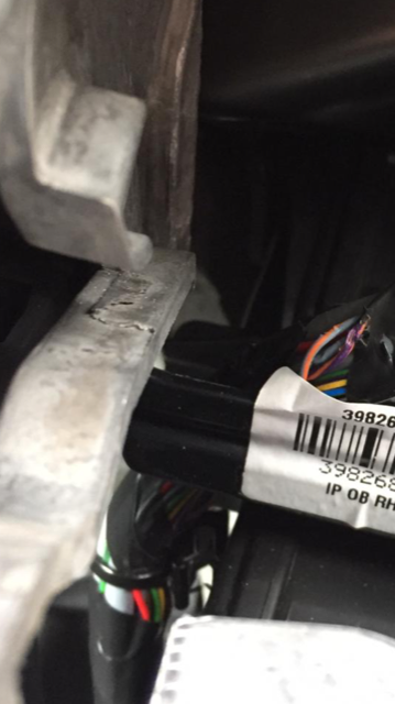
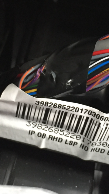
One of the Mid Speed CAN Bus network wires was found to be touching a metal bracket behind the radio.
The wiring was repaired and a foam pad attached to the metal bracket for additional protection against future issues.
The CAN network now preformed as expected.
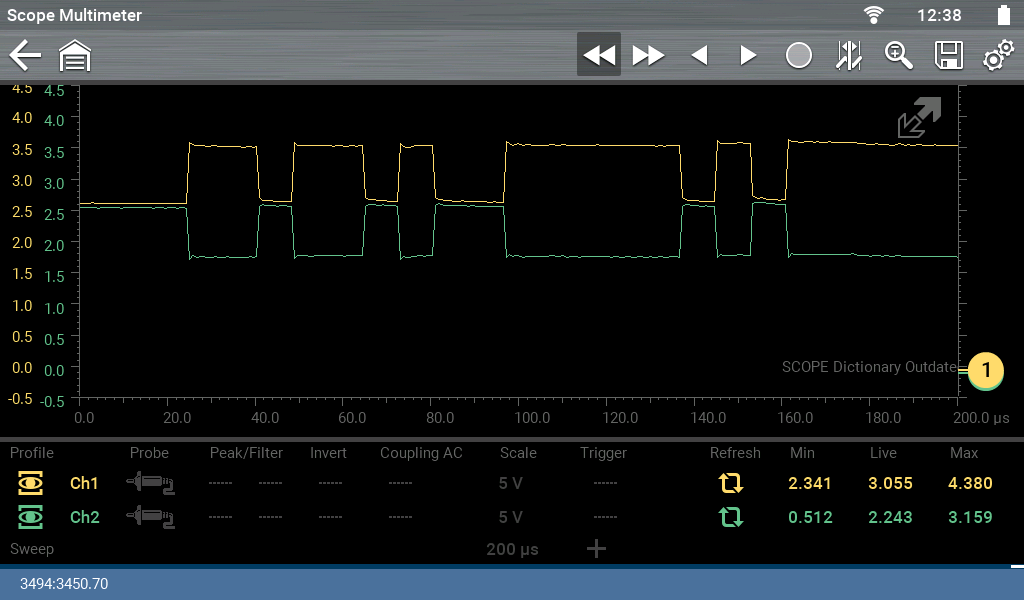
Mid Speed CAN Bus data signal
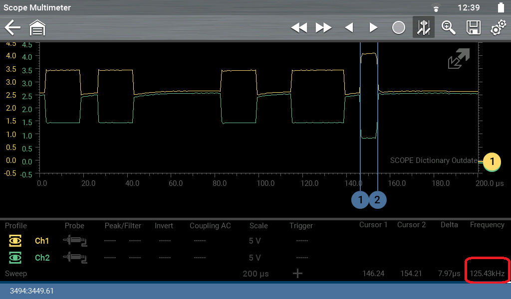
Data Transfer Speed calculated from End of Frame Bit (EOF) – 125 Kbits per Second.
Differential Voltage between CAN High and Low – Mid Speed CAN Bus Network.
The fault codes were erased and the vehicle reassembled. A Road test was carried out and the vehicle preformed as expected. This repair would have been very difficult without the correct wiring diagram for the vehicle, a scan tool to access the fault codes in each system and an oscilloscope to monitor the CAN bus signal.
