Scanner - Automotive
Scanner is a menu driven application that communicates with vehicle control modules to access diagnostic trouble codes (DTCs), parameter data (PIDs), functional tests, and more.
Menus, options and procedures may vary by vehicle. The following instructions apply to most OBD-II vehicles. Not all vehicles support the Auto ID and, or Instant ID feature.
| 1. | Turn the vehicle ignition switch on. |
| 2. | Connect the data cable to the vehicle DLC. See Data Cable / Connections (see below). |
The diagnostic tool will turn on automatically when connected to the vehicle.
| 3. | Select Scanner |
While using the Scanner and OBD-II/EOBD functions, on-screen data cable connection instructions are provided. The instructions may include the location of the vehicle DLC.
| 4. | Depending on the vehicle, Instant ID may occur. |
| 5. | If Instant ID is not supported, after selecting vehicle make (and year if needed), choose Automatic ID or Manual ID and enter the vehicle information at the screen prompts to continue. |
If Automatic ID is selected, the identification process automatically completes (if supported by the vehicle).
| 6. | Select a VehicleSystem (e.g. Engine, Transmission). |
| 7. | Select a Vehicle System Test/Function (e.g. Codes Menu) to perform. |
Damage to the vehicle electronic control module (ECM) may occur if communication is disrupted. Make sure the data cable is properly connected at all times during testing. Exit all tests before disconnecting the data cable or powering down the diagnostic tool.
The Scanner function remains open as long as there is an active communication link with the vehicle. You must interrupt this communication link in order to exit from tests and power down the diagnostic tool. A warning message displays if you attempt to shut down while the diagnostic tool is communicating with the vehicle.
| 8. | To exit Scanner vehicle communication, select the Home icon then select Exit Vehicle from the Quick-Access menu. |
If your diagnostic tool and data cable are compatible with Ethernet communication, It will connect to the vehicle automatically.
If your diagnostic tool and/or data cable are not compatible with Ethernet communication, when you try to connect you may be prompted to connect a special data cable. For example, "Use the DA-4EA Ethernet adapter cable. This vehicle is equipped with and Ethernet communications system. Please see your sales representative for more information."
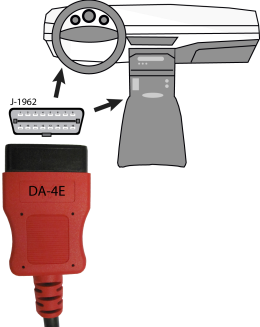
In order to communicate via Ethernet, follow the prompts on the diagnostic tool to use the data cable marked “DA-4E” or “DA-4EA” . Substituting a different data cable may result in no or an erroneous communication condition.
Snap-on supports Ethernet communication for select Jaguar, Land Rover and Volvo models.
Only use the supplied data cable, and/or original equipment accessory cables with your diagnostic tool. Total data cable length must not exceed 114.17 inches (2.9 meters).
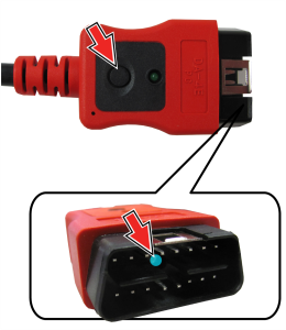
The diagnostic tool will automatically turn on when the Data Cable is connected to a vehicle that has 12VDC at the data link connector (DLC). An LED indicator on the DLC end of the data cable illuminates when power is being supplied. If the LED fails to illuminate, check the data cable connection and then the DLC power circuit.
During vehicle identification, on-screen cable connection instructions may be provided along with the location of the DLC.
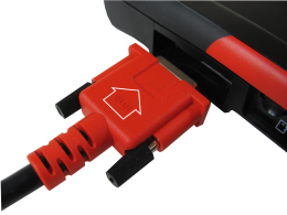
| 1. | For OBD-II/EOBD compliant vehicles, connect the DA-4E data cable (26 pin end) to the diagnostic tool. Connect the cable with the arrow facing up. |
The data cable, includes an LED flashlight on the vehicle DLC connector end. The LED is powered by the diagnostic tool battery
| 2. | Connect the 16‑pin (J-1962) end of DA-4E cable to the vehicle DLC. |
Menus, options and procedures vary by vehicle. Not all vehicles support Auto ID and, or Instant ID.
Depending on the vehicle, the vehicle identification process may require manual entry of the vehicle information, or it may be automated.
| 1. | Turn the vehicle ignition switch on and connect the data cable to the tool and vehicle. |
| 2. | Select Scanner from the Home screen and follow the prompts to enter the vehicle make and year. |
| 3. | If prompted select, Automatic ID or Manual ID. |
| ● | Selecting Automatic ID or the Automatic ID icon |
| ● | Selecting Manual ID will allow you to continue manually identifying the vehicle. |
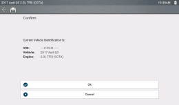
| 4. | Follow the screen prompts to complete the vehicle identification process, then select OK to continue. |
Data cable location and connection information may be provided.
Instant ID automatically communicates with the vehicle to start the vehicle identification process.
Operational Requirements:
| ● | Vehicle requirements: |
| – | Vehicle must support Mode $09 VIN. |
| - | Note:Mode $09 VIN is mandated on 2008 and newer vehicles. |
| – | Vehicle must be equipped with Hi Speed CAN or J1850 communication protocol. |
| ● | Connection procedure requirements: |
Turn the vehicle ignition switch on and connect the data cable to the tool and vehicle.
An audible "beep" will sound approximately 6 seconds after boot-up, if the VIN is read and confirmed select OK to continue .
If the Scanner feature is exited during the session that Instant ID was used, selecting Scanner again, will not ID the vehicle again. To quickly ID the vehicle again, select it from Previous Vehicles and Data > Vehicle History.
Alternative Vehicle Identification
If you try to identify a vehicle that the Scanner does not recognize, you can try and establish communication by using the OBDII/EOBD function.
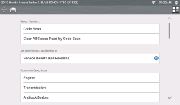
After the vehicle is identified, a menu of available systems and/or test options is displayed .
Use the Menu View icon ![]() to toggle between a categorized and non-categorized list view.
to toggle between a categorized and non-categorized list view.
Select a System / Test option as applicable.
Only the systems/ test options supported for the vehicle are displayed.
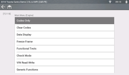
Typical System Main Menu options.
Once a system/test option is selected, the available options for that system are displayed in the System Main Menu .
Menus and navigation will vary by vehicle.
The System Main Menu may include:
| ● | Codes Menu—displays diagnostic trouble code (DTC) records from the vehicle electronic control module. Selecting may open a submenu of viewing options. |
| ● | Clear Codes—erases DTC records and other data from the ECM. This selection is found on a Codes submenu for some models. |
| ● | Data Display— displays PID data from the vehicle electronic control module. Selecting may open a submenu of viewing options. |
| ● | Functional Tests—provides specific subsystem tests. The tests vary depending on the manufacturer and model. |
| ● | Actuator Tests—similar to functional tests, checks the operation of certain actuators, such as solenoid valves and relays. |
| ● | Memory Resets—allows you to reprogram adaptive values for certain components after making repairs. Selecting opens a submenu. These options are found on the Functional Tests Menu for some models. |
| ● | System Tests—provides specific subsystem testing. Performing these tests is similar to functional tests. |
| ● | Generic Functions—lets you access certain available Generic OBD II functions from a proprietary menu (1996 and newer vehicles only). |
| ● | Troubleshooter—provides step-by-step procedures, integrating PIDs and retrieving trouble codes when appropriate, for specific symptoms of the identified vehicle. |
