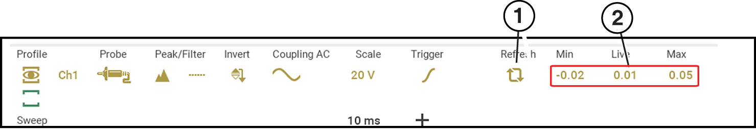
The Trigger feature is only available in the lab scope function.
A trigger can be used to stabilize a changing or erratic signal (a signal that may flicker or drift as it refreshes), so that it is easier to view or diagnose. This stabilization effect is accomplished by basically displaying the same part of the trace repeatedly from the same starting point, thus the flicker or drift is minimized which makes the trace appear more consistent or static.
A trigger is basically a “specific point” on the display, at which a trace will start to display (start the sweep) if it crosses that point.
The trigger feature allows you to set the conditions of that “specific point” also called a “trigger point”. When the trigger conditions are set, and a trace “meets” those conditions (crosses the trigger point), the trace will start.
Trigger Conditions
|
| ●
|
Vertical scale position (amplitude) |
|
| ●
|
Sweep position - the horizontal scale position, or position in time |
|
| ●
|
Slope direction - the direction the trace must be moving (up/rising or positive) or (down/falling or negative) when crossing the trigger point. |
Triggers can be set on any channel, however only one trigger can be activated (used) at a time.
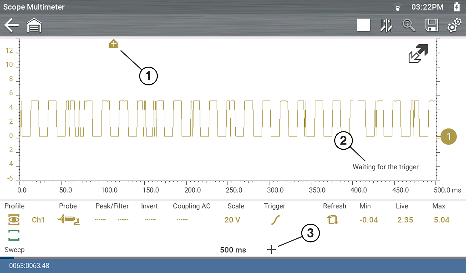
If a trigger is set outside the range of the scales, a yellow marker (e.g. arrow with plus symbol) will be displayed indicating the trigger is out of range and a confirmation screen will display.
When a trigger is set on a channel, and more than one channel is active (displayed), trigger conditions must be met for that channel in order to display all the other channels.
Turning Triggers on/off
A trigger is activated by selecting the trigger icon from the control panel, which then automatically initiates trigger slope setup.
|
| 1.
|
Select the desired channel’s Trigger icon. |
Each tap of the icon sets the trigger to a different slope setting, or turns the trigger off.
|
| 2.
|
Select the desired slope setting, to turn the trigger on. |
|

|
Rising (up or positive) - Trigger is turned on to start the trace on the rising edge (as signal begins to rise)
|
|

|
Falling(down or negative) - Trigger is turned on to start the trace on the falling edge (as signal begins to fall)
|
|

|
Off - Trigger is turned off.
|
|
| 3.
|
Proceed to “To set trigger position” next to complete the trigger set up. |
Setting Trigger Position
Trigger position (also called trigger level) can be adjusted in two ways:
|
| –
|
Dragging the trigger marker on the touch screen - rough adjustment |
|
| –
|
Using the trigger position control panel - fine adjustment |
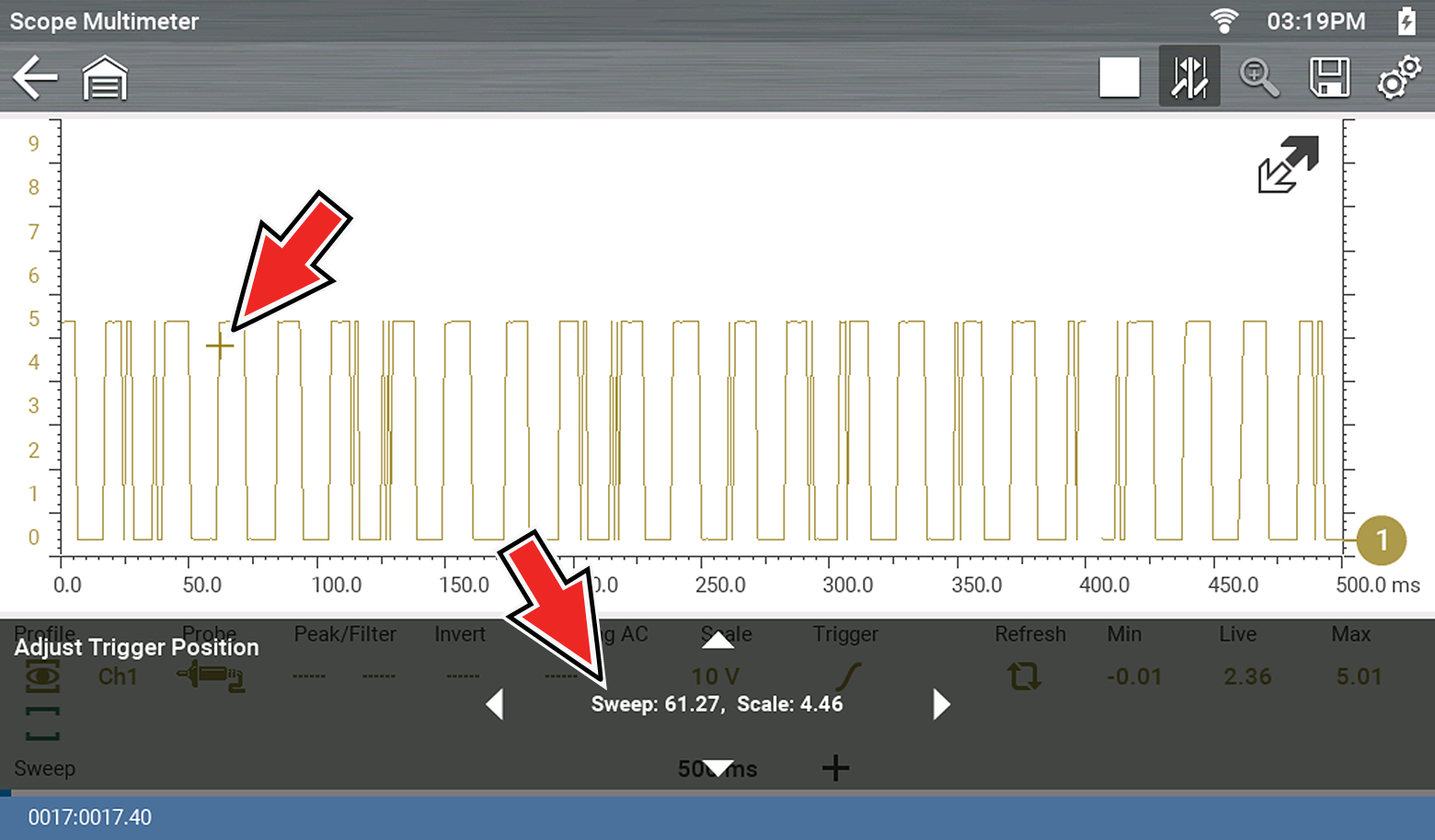
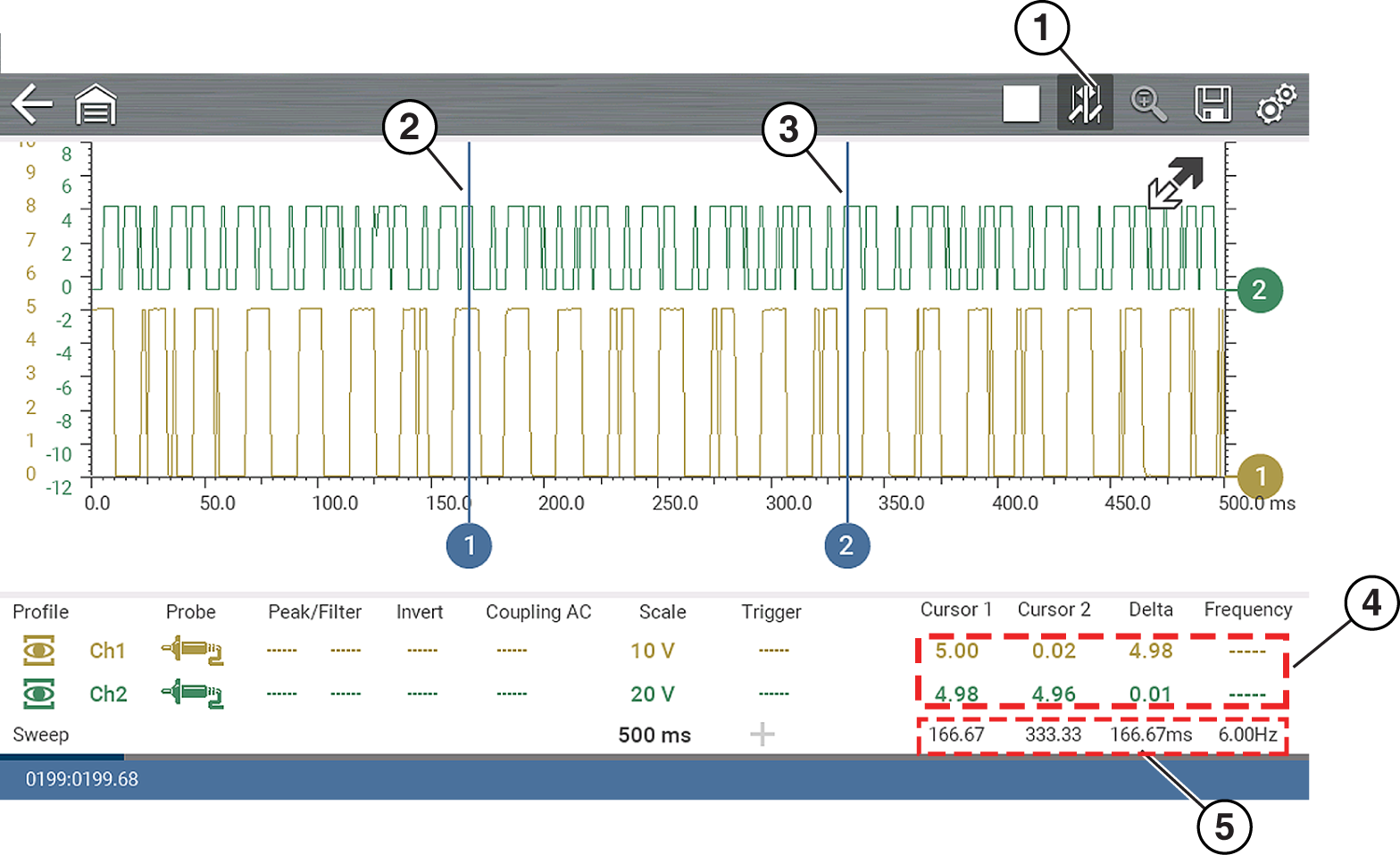
The trigger marker is indicated by a plus symbol (+) on the display . The trigger marker represents the trigger point and is displayed on the screen when the trigger is turned on.
To roughly position the trigger marker, select and drag it into position using the touch screen.
|
| 4.
|
To more accurately position the trigger marker, select the Trigger Position Control icon . |
The trigger position control panel opens.
|
| 5.
|
Use the directional controls provided, or the thumbpad directional controls to move the trigger marker into position. Sweep and vertical scale values are provided in the trigger position control panel, which gives you the precise position of the trigger marker. |
|
| 6.
|
Press the N/X button, to exit. |
Trigger Auto/Manual Mode (Optional Setting)
The Auto and Manual Trigger modes allow you to set the criteria used to display signals on the screen. To change the trigger mode, the trigger must be set on one of the channels.
In both Auto and Manual Trigger mode the screen is updated when the signal crosses the trigger point in the selected direction (rising or falling), however:
|
| ●
|
Auto Trigger—(default mode) |
|
| –
|
when Auto Trigger is on, even if the signal does not cross the trigger point, the screen automatically updates after a short period (approximately 1/2 second) allowing you to see the waveform. When this occurs, the message "Waiting for the trigger" is displayed on the screen. The trigger point can then be set to optimize viewing. |
|
| –
|
when Manual Trigger is on, if the signal does not cross the trigger point the screen will not update. This allows you to capture intermittent events, as the screen only updates when the signal meets your trigger selection. |
To use Manual Trigger, it may be easier to initially set the trigger point using Auto Trigger, as the screen will update regardless if the signal crosses the trigger point. Once the trigger point is set, then switch to Manual Trigger mode.
Selecting Trigger Auto/Manual Mode
|
| 1.
|
From the Control Panel (on the test meter screen), turn the trigger on for the desired channel. |
|
| 2.
|
Select the Settings icon from the toolbar. |
Home Screen: Settings> Configure Scope / Meter > Trigger Mode
|
| 3.
|
Select either Auto Trigger or Manual Trigger. |
|
| 4.
|
Select Back or press the N/X button to navigate back to the test meter screen. |