Some of the leads, probes and adapters supplied with or that may be available, are explained in the following section.
Not all test leads and/or accessories may be available in all markets. Contact your sales representative for information, or to find out more about these and other available accessories.
Avoid damaging test leads, do not pull on the wire when removing the leads from their jacks. Pull only on the lead terminal end.
The shielded yellow lead is used with channel 1, and is color matched with the channel 1 jack on the diagnostic tool.
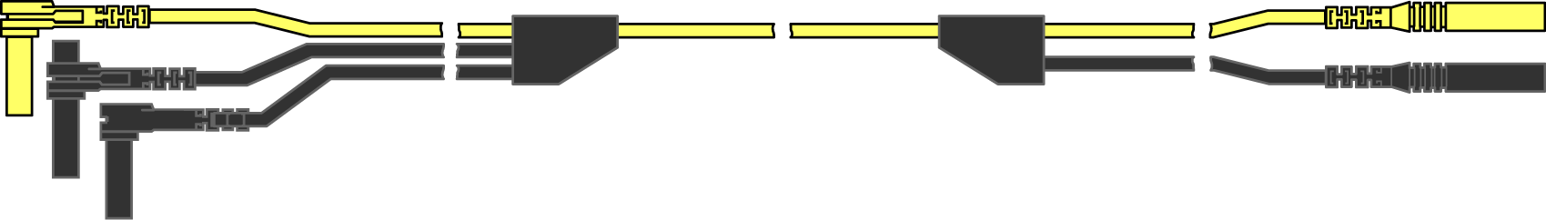
This lead also includes two black, right-angle common ground plugs. One plug is standard and the other is stackable. The standard ground plug should always be connected to the ground (GND) jack on the diagnostic tool.
The stackable ground plug is used for connecting additional ground leads, such as the Channel 2 or the Secondary Coil Adapter lead grounds. The stackable ground lead is internally connected to the standard ground lead, therefore it does not need to be connected to the diagnostic tool ground jack.
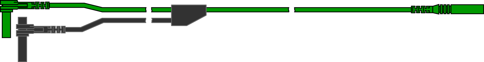
The shielded green lead is used with channel 2, and is color matched with the channel 2 jack on the diagnostic tool. This lead also includes a black, right-angle stackable ground plug.

The secondary ignition adapter lead can be used with the secondary ignition clip-on wire adapter, coil-in-cap (CIC), or coil-on-plug (COP) secondary ignition adapters to display secondary ignition signals. The clip-on adapter clips over a secondary ignition wire to pickup a signal, and the CIC and COP adapters attach to the ignition coil. The coil adapter lead includes a black, right-angle stackable ground plug, and a RCA type connector that is used to connect the lead to a secondary ignition adapter. The spring clamp is used to connect to a ground.
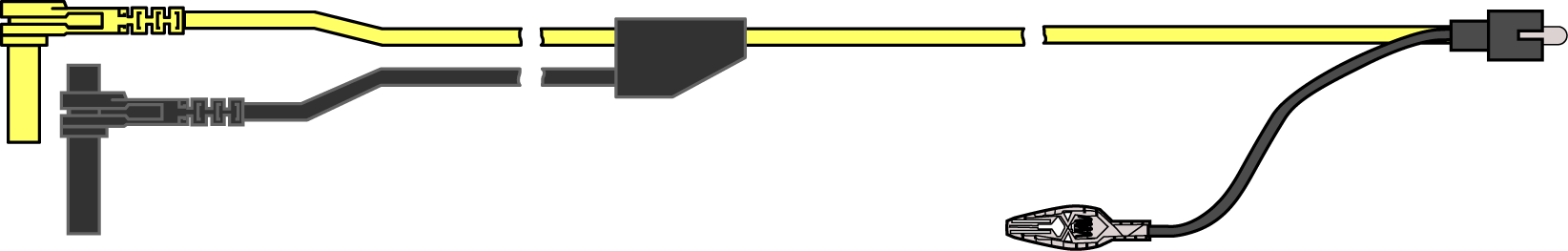
Secondary Ignition Coil Adapter Lead
Clip-on Wire Adapter
Contact your sales representative for additional information on OEM specific CIC and COP secondary ignition adapters.
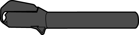
The Low Amp Current Probe is used measure AC or DC current up to 60A. This probe includes two scales (0 to 20A) and (0 to 60A) that can be used to provide accurate and reliable non-intrusive current measurement for components such as, ignition coils, fuel injectors, fuel pumps, relays, and electric motors.

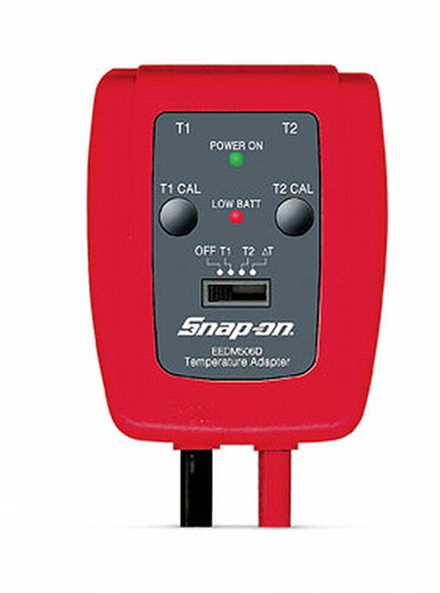
Different pressure transducers and adapters are available for measuring positive and negative gas and liquid pressures. Depending on the adapter, measurement capabilities range from 1 to 5000 psi and up to 29 inHg. Measurement and application capabilities vary per device.
![]()
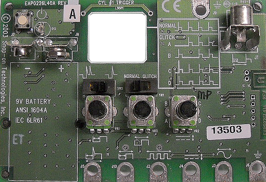
To help you sharpen your lab scope and graphing multimeter skills, optional waveform demonstration tools are available as a training aid. These demonstration tools generate common waveforms, and allow you to vary their display characteristics by turning glitches on/off, helping you to become more familiar with the lab scope controls. Common waveforms include, AC sine wave, variable frequency and pulse, secondary ignition, and more.
There are two tools currently available, the standard model (lower image) and the vehicle simulator model (upper image) which produces waveforms (e.g. Crankshaft Position Sensor (CKP), Camshaft Position Sensor (CMP), Accelerator Pedal Sensor (APP), Wheel Speed Sensor (WSS) Signals, and more) representative of a 2012 BMW 328i Sedan.