2016 Mercedes E350
by Jason Gabrenas and Mike Reynolds
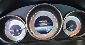
This vehicle had been in a collision and repaired, however they were unable to deliver it as a warning message indicating ‘lane keeping assist inoperative’ was displayed in the instrument cluster.

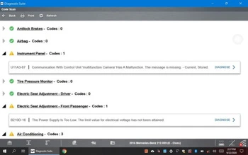
A code scan with the ZEUS® revealed a code for loss of communication with the multifunction camera.
The first step in our diagnostic approach for this code will be to look at the wiring diagram and use it to determine the most likely potential causes of our loss of communication. In this case the circuitry is very simple: one power, one ground, and two CAN communication circuits.
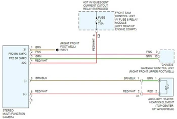
The multifunction camera is located on the windshield of this vehicle. Because this vehicle was in a collision, our thought is that the most likely causes would either be a camera left unplugged after a windshield replacement, a blown fuse that could have been shared with other components, or wiring that could have been damaged in the accident. After checking to make sure the camera was plugged in, we accessed the front SAM (Signal Acquisition Module) and verified that there was power on both sides of fuse 13.
Check out Guided Component Tests on compatible Snap-on platforms for vehicle specific waveforms and pin assignments.
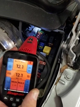
Just because our fuse was blown, doesn’t mean that the power is getting to the camera. Moving our testing to the camera itself, we verified power and ground at the camera. Since this circuit is protected by a 7.5-amp fuse, it was unlikely that the camera could pull more than an amp or two which tells us that voltage drop is highly unlikely as a cause of this fault.
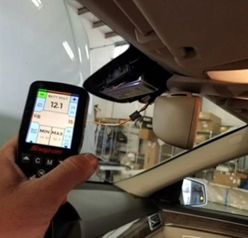
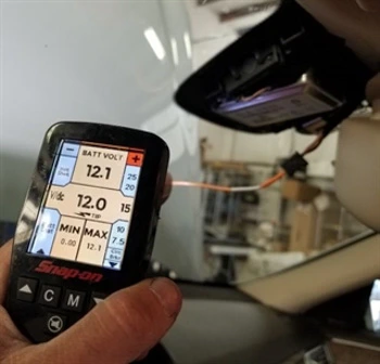
With power and ground to the module, the only thing left to check was the CAN signal at the camera.
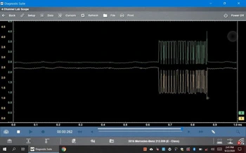
We use the camera’s ground and connect one scope lead to each CAN circuit and dial in the waveform.
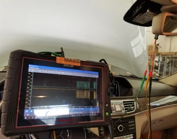
Looking at the CAN waveform, we see a clean looking signal. The CAN high and low mirror each other consistently. With that information, we verified all signals to the camera are good, so we recommended replacing the camera.
