TECHNICAL REFERENCE
Released by Snap-on Diagnostics
June 2024
Keith Wray
Snap-on® Diagnostic National Trainer
Anti-lock Braking System (ABS) – Stop, in the Name of Safety
Brake System Evolution
I have always been meticulous about repairing brake systems. Years ago, on drum brakes, barring any fluid leaks, I wrote the estimate to include a spring kit, along with the shoes, at a minimum. I wire-brushed the backing plate to be spotless followed by applying high temp lithium grease on the contact areas of the backing plate to prevent sticking brake shoes. I would not cut corners to save someone a couple of dollars. Thankfully, ABS technology has made it exceedingly difficult for anyone to cut corners. This is a great thing when it comes to safety.
A Short History on ABS
The concept of ABS was introduced in 1908 by J.E. Francis rolling out his “Slip Prevention for Rail Vehicles.” In 1920, the French automobile and aircraft pioneer Gabriel Voisin worked on developing systems on his aircraft brakes that would reduce tire slippage. Two patents came along between 1928 and 1936, one of which was awarded to Robert Bosch of magneto ignition system fame. The first fully electronic ABS was developed in the late 1960s for the Concorde aircraft. The modern ABS made its way to the automotive industry via Ford in 1969, Fiat Research Center in 1971 and Toyota in 1971. Motorcycles jumped on board with BMW in 1988.
Regulations
In Europe and other international markets, ABS is required on all vehicles sold after 2004. ABS wasn’t mandated in the U.S. until 2012.
Results
A study done by Monash University Accident Research Centre concluded that
the multiple vehicle crash risk is reduced by 18% with ABS systems. The Insurance Institute for Highway Safety released a study stating that motorcycles with ABS were 37% less likely to be involved in a fatal crash.
Operation
Anti-lock brakes were developed to enable a driver to remain in control of the vehicle during difficult road conditions. When a wheel locks up, stopping distances increase and the vehicle is impossible to steer. By reducing brake pressure to the wheel that originally lost traction, the vehicle will become controllable. An electronic control module uses the inputs from the wheel speed sensors to calculate the onset of a skid. The module is usually mounted on the hydraulic modulator assembly. See the basic components below.
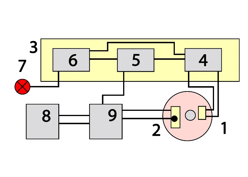
1) Wheel speed sensor
2) Wheel brake assembly
3) ABS control module
4) Wheel speed calculation stage
5) Brake pressure control stage
6) Fault monitoring stage
7) ABS warning light
8) Master cylinder/brake booster
9) Hydraulic modulator
In a nutshell, the electronic control unit (ECU) constantly monitors each wheel speed sensor. When it detects a wheel rotating slower than the vehicle speed, it knows a wheel has lost traction. It actuates the valves to reduce hydraulic pressure to the brake at the affected wheel, thus reducing the braking force on that wheel.
Next, if the ECU detects a wheel turning faster than the others, hydraulic pressure to the wheel is increased so the braking force is reapplied, slowing down the wheel. This process is repeated continuously and can be detected by the driver via brake pedal pulsation. Some systems can apply or release braking pressure 15 times per second.
When working correctly in normal conditions, an ABS-equipped vehicle is nearly impossible to lock up.
If a fault develops in any part of the ABS, a warning light usually is illuminated on the vehicle instrument panel and the ABS will be disabled until the repair is made.
A close cousin to ABS is traction control system (TCS). It is related because it uses the same components that control braking traction during acceleration.
ABS Benefits
| Maintain control |
prevents lockup, allowing a higher level of control during panic stops |
| Traction |
grabs the road substrate on wet, icy or gravel roads |
| Shorter stops |
reduces stopping distance |
| Enhanced steering |
when active, driver can continue to steer even with hard braking |
ABS Limitations
| Decent tires |
worn out tires impact its effectiveness |
Diagnosis
The ABS controller powers on to self-test every time you turn on the ignition. If that controller gets insufficient data, or a hydraulic pump or valve isn't responding, it illuminates the ABS light on the dashboard.
Here a scan tool will reveal any trouble codes.
ABS codes are very comprehensive. For this example, I picked a random BMW, which had almost 50 different ABS codes. That focused level of code description really shortens the list of potential problems. Don’t misunderstand that statement. Even though it narrows the possibilities, component testing is required to verify the actual fault.
In the sample below, we are using the guided component tests to pinpoint the problem. First, we review information about the system on this year’s make, model – system operation, best test location and how to hook it up.
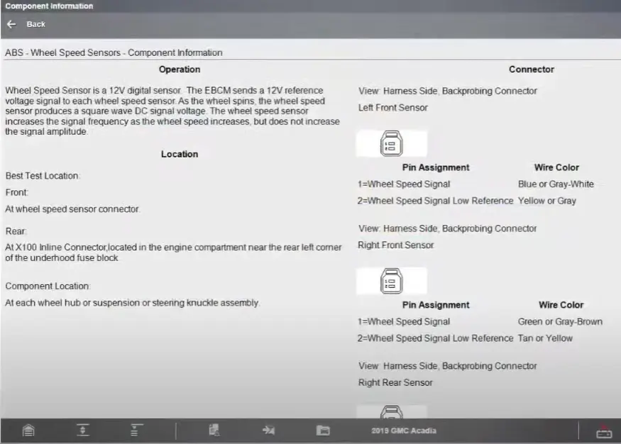
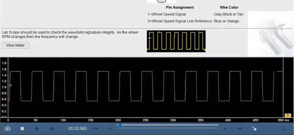
Next, we go live with a lab scope looking at a wheel speed sensor on this vehicle. We can simply compare it to a known good pattern to analyze the signal going to the ABS module.
If I have a wheel sensor driver’s front trouble code, it could be a sensor, but it could also be the ABS module or wiring.
This test shows the sensor signal is good. If connectors and wiring, including power supplies and grounds to the control module, all check good, then a new module should take care of this issue.
Remember that a relearn or reset may be required depending on the OEM.
Click here for more on this topic, and for so much more, visit Snap-on’s technical article pages.