Take the challenges out of diagnosing modern air/fuel ratio sensors by using this testing process in Snap-on® scan tools with up-to-date diagnostic software.
Modern air/fuel ratio sensors can sometimes bring a little bit of confusion as they are sometimes misunderstood and can be hard to test.
You certainly can't test amperage with them using a lab scope. You need to utilize the scan data to see what the air/fuel ratio sensors are doing and whether or not they are it's actually working properly.
We will cover how they work and then we'll go through the scanner and see how to test them.
Let's review some information about how they work first. We will be using a tool with Guided Component Tests in it.
We'll go into the Guided Component Tests menu, to the Fuel Injection System, and there it is – Air/Fuel Ratio Sensor.
The first step should always be Component Information. There we can learn how this sensor works.
The sensor contains a pumping cell and a reference cell separated by a porous diffusion gap. So basically, it's like two oxygen sensors together in a sandwich.
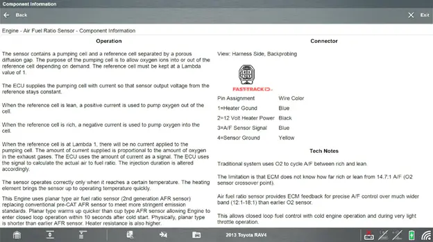
The purpose of the pumping cell is to let oxygen in to or out of that reference cell, depending on whether it's needed or not.
The computer is always trying to keep that reference cell at a lambda value of one or a metric which would be 14.7 to one air/fuel ratio.
To do that, the ECU supplies the pumping cell with current so that the sensor output voltage from the reference stays at a constant. It's trying to keep that reference voltage the same.
- When the reference cell is lean, a positive current is used to put more oxygen out of the cell.
- When the reference cell is rich, a negative current is used to put oxygen into the cell.
- When that reference cell is at lambda, there is zero current applied to that pumping cell.
So, the amount of current supplied is proportionate to the amount of oxygen in the exhaust gases.
The sensor operates correctly only when it reaches a certain temperature, so these things get very hot, very fast.
Newer sensors get hot enough, 1,250 degrees Fahrenheit, within 10 seconds.
Also remember, output is opposite of what you'd see with a normal oxygen or a conventional oxygen sensor.
It’s a higher voltage under lean conditions and lower voltage under rich conditions, which is the opposite of how a normal oxygen sensor would work.
It is also reacts a lot faster, because the signal lines are biased with about 2.9 to 3.3 volts.
So, when it's just sitting there, you'll see around 2.9 to 3.3 volts.
Let’s create a custom data list.
So, let's go into the scanner and see what we can get on data. Go into Engine then Data Display AF Sensor Data.
A whole lot of data is shown but we don’t really need a lot of it so let’s pare it down using a custom data list.
Hit Custom, then deselect everything, and in this instance, we just need to select AF Lambda, AF Current, AF Voltage and I’d also like to see what the Short-Term Fuel Trim is doing in relation to those.
Go back to the list and graph them all up if you want to. You then need to start up the vehicle and see what the graphs show.
You can see where it started up, at idle, and the computer is trying to keep that lambda back to around one.
So right now, we're looking at 1.0 and notice the current is zero and will remain there as long as lambda stays close to 1.0.
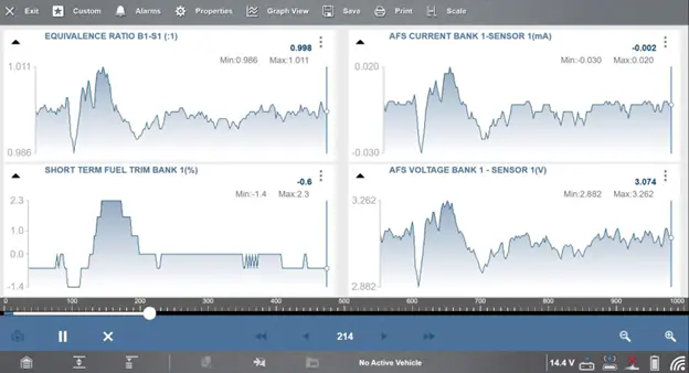
We can see that the voltage is 3.3 volts.
When we hit the throttle a couple of times you can see how quickly the signal reacts. Three quick jumps in succession. Everything follows everything else. The short-term fuel trim reacts very quickly as well.
This is the reason why these vehicles are so good with fuel economy and can adjust their fuel so quickly, by using those air/fuel sensors.
Date posted: July 22, 2024