Selecting OBD Diagnose provides the following menu options (described in the following sections):
Selecting Start Communication, initiates an OBD test session.
| 1. | Select Start Communications. |
| 2. | Connect the Compact Scan Module to the vehicle. |
| 3. | Select Continue. |
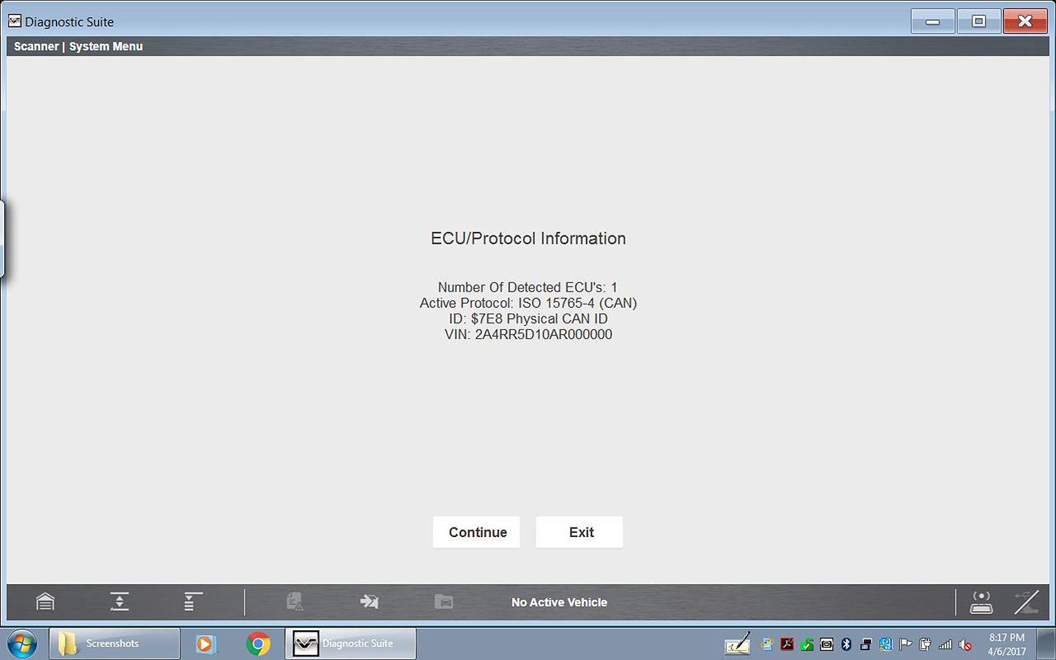
The following information may be displayed:
| – | Number of ECM’s detected |
| – | The communication protocol being used |
| – | Which ECM is actively communicating |
| – | Vehicle Identification Number (VIN) |
| 4. | Select Continue. |
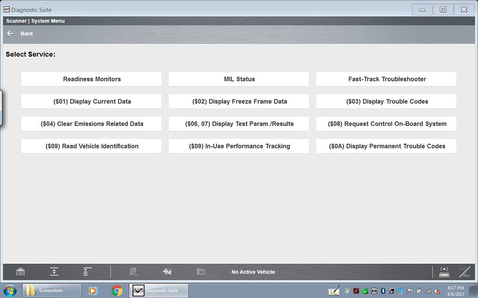
| 5. | Make a selection from the available service menu options. |
Common options are described in the following sections.
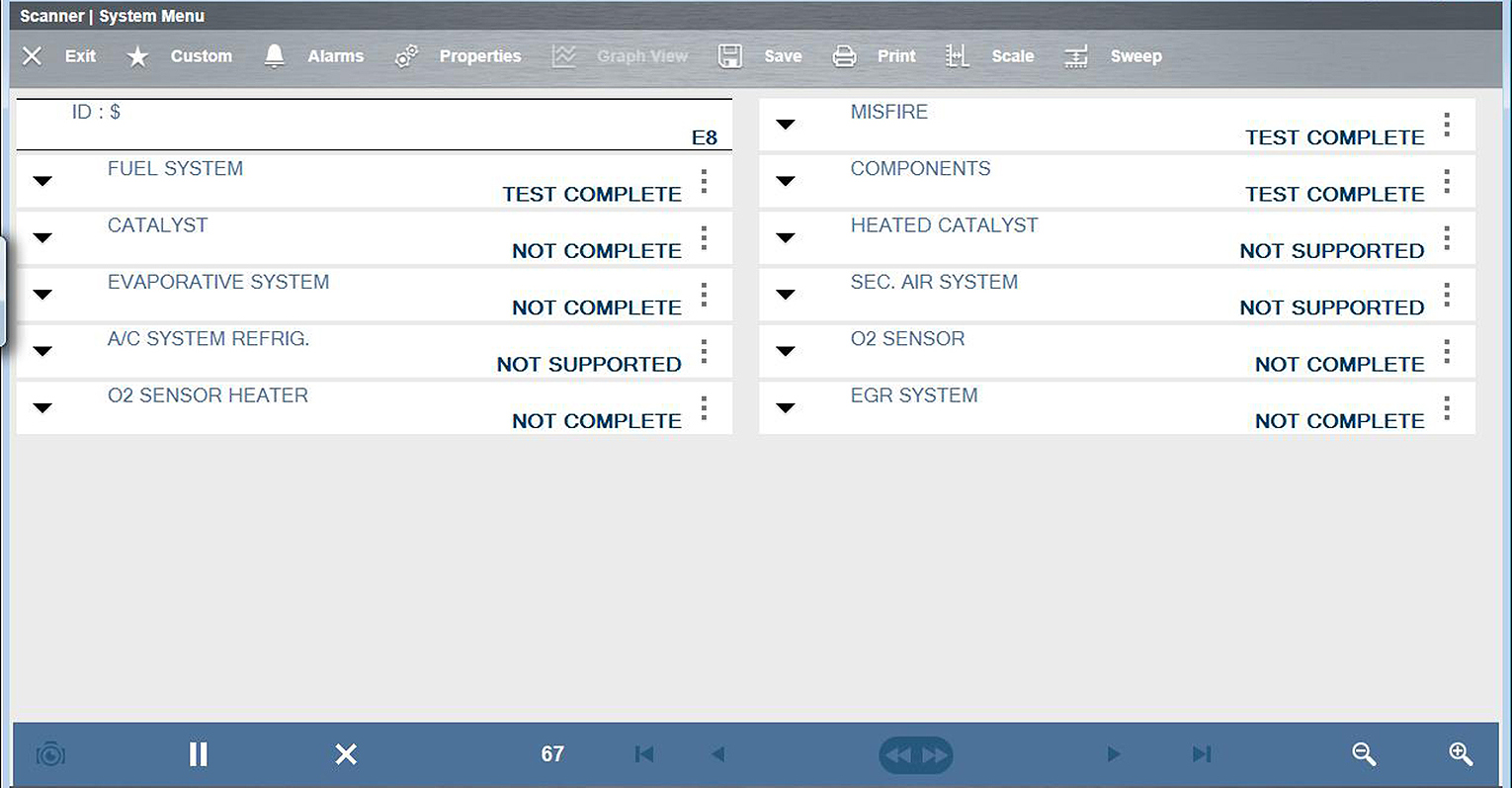
Selecting Readiness Monitors provides the following menu options:
| ● | Monitors Complete Since DTC Cleared—displays the results of all monitor tests that have run since the last time the electronic control module (ECM) memory was cleared. |
| ● | Monitors Complete This Cycle—displays only the results of monitor tests that ran during the current drive cycle, they reset when the ignition is switched off. |
Readiness Monitors is used to check the status of the OBD-II/EOBD monitored systems. Certain emission-related OBD-II/EOBD systems are self monitored by running continuous or periodic tests. Test results (e.g. Test Complete, Test Not Complete, Test Not Supported, etc.) are shown in the data viewer.
Functionality and toolbar options are similar to using the PID Display within Scanner.
OBD-II Modes include emission related data and tests supported by the vehicle manufacturer. Vehicle manufacturers are not required to support all modes.
|
Name |
Description |
|
($01) |
Displays the current emission related data (PIDs) from the selected electronic control module (ECM) of the vehicle. Displayed data includes analog inputs and outputs, digital inputs and outputs, and system status information broadcast on the vehicle data stream. |
|
($02) |
Displays freeze frame data for any stored emission related diagnostic trouble codes (DTC). In most cases the stored frame is the last DTC that occurred. Certain DTCs, those that have a greater impact on vehicle emission, have a higher priority. In these cases, the highest priority DTC is the one for which the freeze frame records are retained. Freeze frame data includes a “snapshot” of critical parameter values at the time the DTC set. |
|
($03) |
Displays any stored emission related DTCs reported by the various ECMs. |
|
($04) |
Clears all emission related diagnostic data such as, DTCs, freeze frame data, and test results from the memory of the selected ECM. |
|
($05, 06, 07) |
Opens a submenu of test parameters and test results from various sensors, monitor test results, and a record of DTCs detected during the last drive cycle. The menu includes: Oxygen Sensor Monitoring ($05) On-Board Monitored Systems ($06) DTCs Detected During Last Drive ($07) |
|
($08) |
Allows enable/disable control of select components, allowing you test component operation and monitor data during the test. Available options vary by make, model, and year of the test vehicle. |
|
($09) |
Displays: Vehicle Identification Number (VIN) Calibration Identification Calibration Verification Number (CVN) |
|
($09) |
Displays the “In-use Performance Tracking” of monitored data (total number of times each monitored test has completed). |
|
($0A) |
Displays a record of any “permanent” codes on late-model vehicles if the vehicle supports Service $0A. A permanent status DTC is one that was severe enough to illuminate the MIL at some point, but the MIL may not be on at the present time. Whether the MIL was switched off by clearing codes or because the setting conditions did not repeat after a specified number of drive cycles, a record of the DTC is retained by the ECM. Permanent status codes automatically clear after repairs have been made and the related system monitor runs successfully. |
MIL Status is used to check the current status of the malfunction indicator lamp (MIL). Additional information, such as which ECM commanded the MIL on, and also (if supported) the distance traveled while the MIL is on, can also be displayed.
Selecting Connector Information provides you access to vehicle data link connector (DLC) location information.
| 1. | Select Connector Information. |
| 2. | Select a vehicle manufacturer. |
| 3. | Select a vehicle model. |
DLC location information displays.
| 4. | Select Continue. |
A menu option to start vehicle communication, or return to the previous menu displays.
| 5. | Select Yes or Return. |
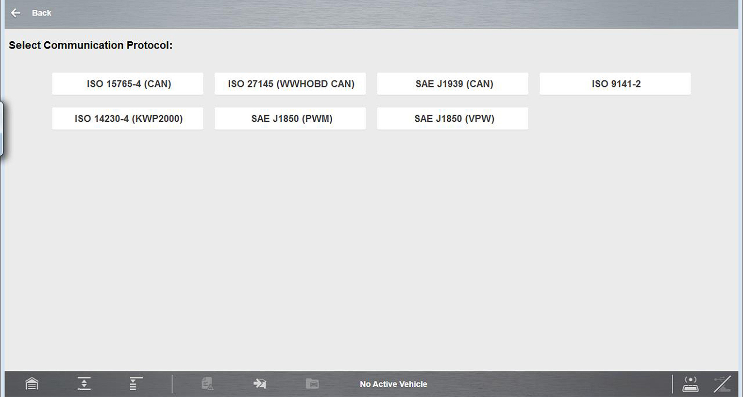
A communication protocol is a standardized way of transmitting data between an ECM and a scan tool. Normally the scan tool automatically connects to an available protocol, which displays on the connection message. Some vehicles communicate using more than one protocol, therefor the Manual Protocol Selection option is used to switch to a different protocol.
Selecting Manual Protocol Selection displays a warning message advising you to make sure you know the correct protocol for the test vehicle before continuing. An incorrect selection may activate warning lamps, and set CAN related faults on the vehicle.
Selecting OK displays a menu of protocol options.
Select the desired protocol to continue.


