To use the Compact Scan Module (CSM) with the diagnostic tool it must be paired to the diagnostic tool.
The Compact Scan Module (CSM) is already paired from the factory.
= Home Screen > System Settings > Paired Devices
Selecting Paired Devices displays the active devices that are paired to the diagnostic tool.
| ● | For Compact Scan Module pairing information, see "Pairing" below. |
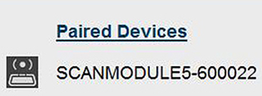
The Paired Devices screen (sample shown below) lists all of the devices paired to the diagnostic tool . The icon indicates the connection and communication status.
To use the CSM, it must be paired with the diagnostic tool.
Pairing is the wireless connection (identification) process used to connect the device to your diagnostic tool.
The device only needs to be paired once before its initial use. The connection configuration should remain in memory for all future uses, unless the connection configuration is removed or lost.
Wireless devices shown in this section are used as reference. Not all devices shown may be applicable to your diagnostic tool.
| 1. | Turn on the diagnostic tool. |
The CSM and diagnostic tool must be on when pairing the CSM. Make sure the diagnostic tool has a fully charged battery, or is connected (recommended) to the AC power supply.
| 2. | Connect the CSM to a vehicle data link connector (DLC), or use the supplied USB cable to connect the CSM to the diagnostic tool to supply power to the CSM. |
The green LED on the CSM is illuminated when power is being supplied to the CSM by a vehicle DLC. The blue LED is illuminated when power is being supplied by USB connection.
| 3. | After the CSM is powered (green LED on), from the diagnostic tool select.... |
= Home Screen > System Settings > Paired Devices
| 4. | Select Add from the toolbar, then OK when prompted. |
The diagnostic tool searches for compatible wireless devices, then displays the results.
Search results include all compatible wireless devices detected, and may include multiple Scan Modules if you are in a shop environment where more than one unit is powered on. Available module listings include a partial serial number. Make sure the screen listing matches the last six digits of the serial number of your CSM before continuing.
| 5. | Select your CSM from the results list. |
A progress message displays during the pairing procedure, the Paired Devices screen displays once the procedure completes.
| 6. | After the pairing process completes, select the Home icon on the toolbar to return to the Home screen. The CSM and diagnostic tool are now paired for wireless communication and should automatically connect when both are powered up. |
If a CSM firmware update is available, the CSM will automatically be updated, see Firmware Updates for additional information.
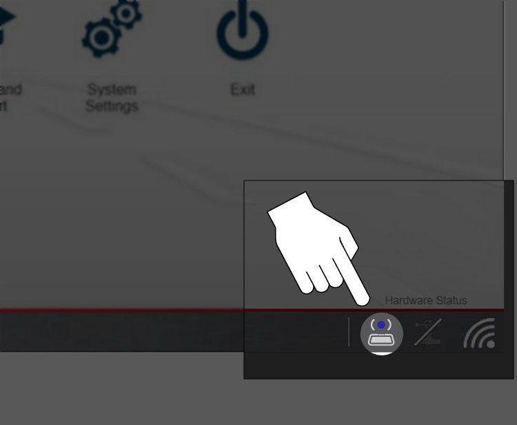
When pairing is successful the CSM hardware status indicator displays on the Home screen (lower-right corner), providing a quick reference to connection status.
For additional CSM information including troubleshooting, see CSM Basic Operation
When the Scope Module is connected (docked or USB cable), it automatically pairs with the diagnostic tool.
To connect using the USB cable, see Using the Scope Module USB Extension Cable.
To pair the Scope Module, dock or connect it using the USB cable then check the connection status by selecting....
= Home Screen > System Settings > Paired Devices
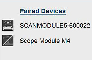
The Paired Devices screen lists all of the devices paired to the diagnostic tool, and also indicates whether or not there is active communication occurring.
The Scope Module will be listed as SCOPE MODULE M4 or similar.
If the Scope Module is not shown in the Paired Devices list, check to make sure it has a good connection. Use the Hardware Status icons shown below to determine connection status,.
The hardware status indicators in the lower-right corner of the Home screen.
|
Status/Icon |
Action |
|
Not Paired |
Indicates the Scope Module is not paired or connected to the diagnostic tool. Pair the Scope Module to the diagnostic tool. |
|
|
|
|
Paired and Communicating |
Indicates the Scope Module is connected and allowing communication. |
|
|
|
|
Paired but Not Communicating |
Indicates the Scope Module USB cable is not connected, or is connected but not allowing communication. Check to ensure the Scope Module is properly connected with the USB cable. |
|
|


