Guided Component Tests
 Selecting Guided Component Tests provides you with an extensive collection of vehicle specific component tests and reference information for engine, transmission, ABS, charging, transfer case, and suspension systems. It is like having access to a complete library of automotive repair manuals for testing multiple vehicle components.
The preconfigured meter tests and reference information provided are vehicle specific and designed to help save you diagnostic time, verify faulty components, and verify the repair.
Detailed instructions and reference information are provided to guide you through the testing process, from locating the component, to selecting the appropriate test, showing test lead connections, and illustrating electrical connector and pin configurations. In addition, test results (including waveform examples), procedures, tips, and specifications may also be provided.
Availability of tests and information may vary.
Safety Information
 Safety Information

Risk of electrical shock.
Read the Important Safety Instructions document provided separately for messages on the safe use of this product.
This product is intended for low voltage systems (for example, automotive 12V systems), do not use this product for Measurement Categories II, III, and IV.
This product is designed for performing measurements on circuits not directly connected to MAINS or MAINS circuits (an example of a MAINS circuit is 120V AC or 240V AC household or industrial electricity), do not connect this product to MAINS or MAINS circuits.
Do not apply the Black Ground Lead to test points other than ground/system return/vehicle chassis.
Electrical shock can cause personal injury, equipment damage, and/or circuit damage.
Maximum rated transient over voltage impulse is 500 volts, do not exceed the rated transient over voltage.
Configuring the Favorites List
 Configuring the Favorites List
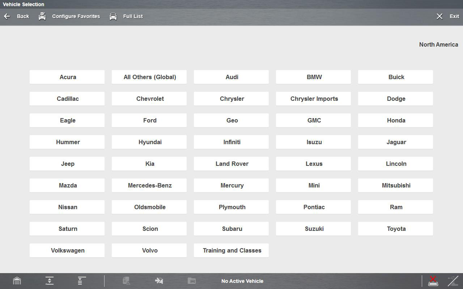
Once a Guided Component Test database is loaded, a list of manufacturers displays. This list is often long and includes makes that are not frequently used. A toolbar at the top of the screen allows you to custom configure the manufacturer list to display only the makes you frequently service.
Sample manufacturer list
|
1.
|
Select Configure Favorites on the toolbar. |
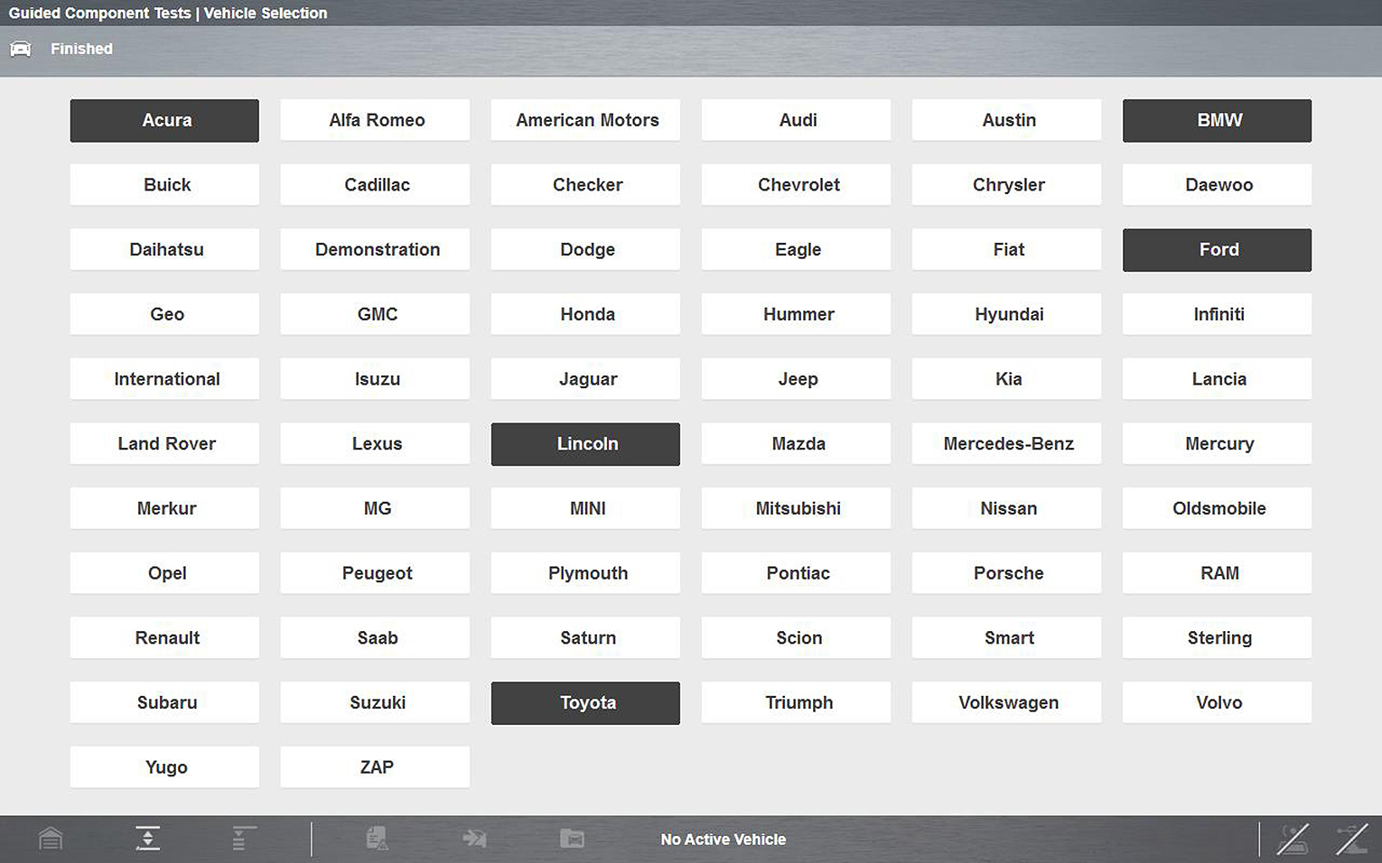
A list of selectable manufacturers displays.
Sample Configure Favorites screen
|
2.
|
Select each manufacturer you want to include, selected manufactures are highlighted. |
Manufacturers appear on the favorites list in the order in which they are selected. Therefore, if you select the makes you work on most frequently first, they will appear at the top of the list.
|
3.
|
Select Finished on the toolbar once your selections have been made. |
The screen returns to the manufacturer list, but only the makes you selected display. Note the “Favorites” toolbar selection now reads “Full list”.
|
4.
|
Select Full List on the toolbar to view the complete list of manufacturers. |
|
5.
|
Select Back on the toolbar at any time to return to the previous screen. |
Your favorites list is what will display whenever a Guided Component Test database is started in the future. The list can be modified at any time by selecting Configure Favorites from the toolbar.
Menu Icon
 Menu Icon

Selecting the Menu icon from the lower toolbar provides the following options:
|
●
|
Help—See Help for additional information. |
File
Selecting File opens a menu of print options: (See Printing / Printer Setup)
|
●
|
Print Article—selecting has one of two results: |
|
–
|
If a printer is connected, the file is sent to the printer. |
|
–
|
If a printer is not connected, the article is saved as a (.xps) file, which can be retrieved, moved, or copied and printed at a later time. |
|
●
|
Print Preview—opens a representation of what the printed file will look like. |
|
●
|
Page Setup—allows you to adjust margins and paper orientation. |
Classes
 Classes
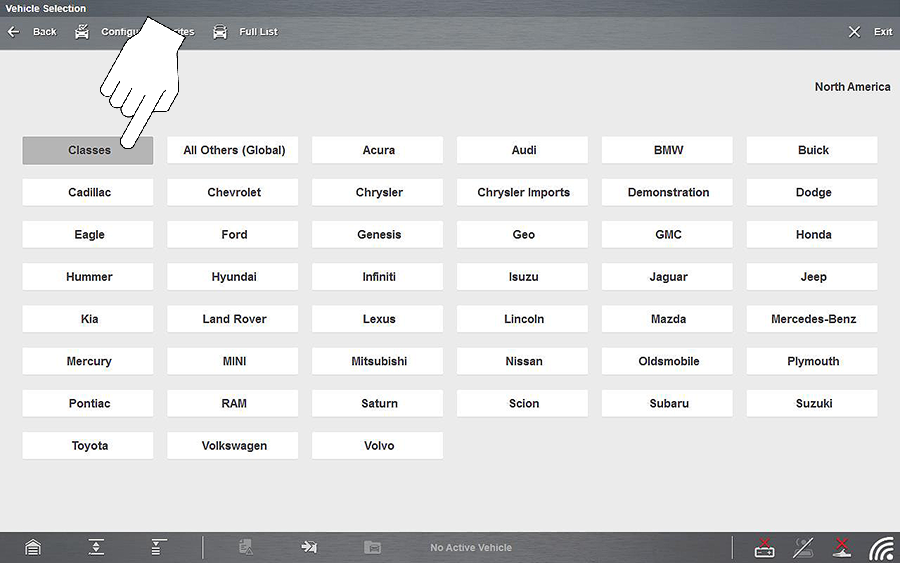
Classes is a companion feature to the Guided Component Tests function, and can be selected from the vehicle make menu, select Classes. This resource includes a wide collection of common (non-vehicle specific) reference information and tests, such as measuring fuel pump current ramp, and monitoring CKP and CMP signals simultaneously. Also included are; basic component operation and theory information, testing procedures, tips, definitions, illustrations, diagnostic tool feature descriptions, and accessory information.
Selecting Classes provides the following options (each option is described in the following sections):
The information listed in the following sections is not inclusive, actual content may vary.
 Power User Tests
Power User Tests provide you quick access to preconfigured meter tests for a number of common automotive system tests. Most tests provide onscreen help and testing information along with a description of the test and the expected results, including known good waveforms.
Here is a sample listing of the types and specific tests that may be available within Power User Tests:
|
●
|
Current Probe Tests - provides common tests configured to use the Snap-on Low Amp Current probes or generic Low Amp Current probes. Snap-on Low Amp Current Probe operation information is also provided within the Snap-on Low Amp Probe Reference Manual option. |
|
●
|
Fuel Injector Current Ramp (multiple types) |
|
●
|
Fuel Pump RPM Calculation |
|
●
|
Ignition Coil Current Ramp (multiple types) |
|
●
|
Snap-on Low Amp Probe Reference Manual |
|
●
|
Two Channel Tests - provides common tests configured to measure or compare two signals |
|
●
|
CKP and CMP Relationship |
|
●
|
EGR Solenoid and Position Sensor |
|
●
|
EVAP Solenoid and Diagnostic Switch |
|
●
|
Injector and Oxygen Sensor |
|
●
|
MC Dwell and Oxygen Sensor |
|
●
|
Pre and Post Cat Oxygen Sensors |
|
●
|
Throttle Positions 1 & 2 |
|
●
|
Transducer Tests - provides common single and dual channel tests configured to measure various types of pressures, voltage and current. Transducers are available as optional equipment. |
|
●
|
A/T Line Pressure and Shift Solenoid |
|
●
|
EGR Temperature Sensor and EGR Vacuum |
|
●
|
Exhaust Back Pressure Test |
|
●
|
Fuel Pressure and Fuel Pump Current |
|
●
|
Fuel Pressure and Fuel Pump Voltage |
|
●
|
Secondary Ignition Tests - provides common information and tests configured to measure secondary ignition output of various types. Secondary ignition lead adapters are available as optional equipment. |
 How To Guide
The How To option provides multiple topics and references ranging from instructional and basic theory to troubleshooting and testing instructions. Menu options may include:
|
●
|
10-minute Electronic Classes—provides basic electrical theory and testing information. Topics may include: |
|
●
|
Guided Voltage Drop Test |
|
●
|
Other Electrical Measurements |
|
●
|
15-minute Ignition Class—provides basic introductory ignition system information. Topics may include: |
|
●
|
Illustrated Terms & Definitions—provides common term definitions, illustrations, and tips associated with automotive component testing. |
|
●
|
No-Start Basics—provides basic step-by-step procedures for the diagnosis of a no-start condition on carbureted and fuel injected vehicles. |
|
●
|
O2 Sensor & Feedback System Analysis—provides basic definition and theory information for the following O2 sensor topics: |
|
●
|
Correct PCM Response (includes configured meter test) |
|
●
|
Non-Heated Oxygen Sensor |
|
●
|
Understanding Oxygen Sensors (includes configured meter test) |
|
●
|
Snap-on Automotive Theory— provides basic theory information on multiple topics including: |
|
●
|
Diagnosing Battery Draws |
|
●
|
Diesel Particulate Filters |
|
●
|
Electronic Parking Assistance |
|
●
|
Supplemental Restraint Systems |
|
●
|
Tire Pressure Monitoring (TPMS) |
|
●
|
Test Tips—provides basic testing information, tips and procedures for specific tests and meter operations. Topics may include: |
|
●
|
Frequency, Pulse Width and Duty Cycle Test |
|
●
|
Injector Pulse Width Test |
|
●
|
Using Pressure Transducers |
|
●
|
Zirconia Oxygen Sensor Rise Time |
|
●
|
Theory and Operation—provides basic theory information for the following topics: |
|
●
|
Oxygen Sensors and Relays |
|
●
|
20-minute Current Ramp Classes—provides an introduction to current ramp testing using the Snap-on Low Amp Current Probes. Snap-on Low Amp Current Probe operation information is also provided within the Snap-on Low Amp Probe Reference Manual option. Topics may include: |
|
●
|
Fuel Injector Current Ramp (multiple types) |
|
●
|
Fuel Pump RPM Calculation |
|
●
|
Ignition Coil Current Ramp (multiple types) |
|
●
|
Snap-on Low Amp Probe Reference Manual |
|
●
|
Using Fuse Box for Current Test Hard to Reach Wiring |
 Features and Benefits
Selecting Features and Benefits provides basic feature description and operational information about the diagnostic tool. Additional information is provided for ShopStream Connect, optional waveform demonstration boards and optional accessories. Selections include:
|
●
|
5-Minute Walk Thru With Demo Board—provides instructions on the operation of the optional waveform demonstration board(s) to sharpen your Lab Scope and Meter skills. Topics may include: |
|
●
|
New Demo Board (PN) #EESX306A—provides functionality information and basic step-by-step demonstration information of multiple generated waveforms |
The optional demonstration board(s) generate various waveforms similar to signals commonly found on modern vehicle control systems. The demonstration board(s) not only help you learn how to use the Guided Component Tests software, it allows you to hone your skills and diagnostic techniques without connecting to an actual vehicle. Contact your sales representative for details.
|
●
|
Accessories—provides descriptions for the optional accessories available for the diagnostic tool. Accessory topics may include: |
|
●
|
Pressure/Vacuum Transducers |
|
●
|
Product Description—provides an overview of diagnostic tool capabilities and operations. |
Vehicle Identification
 Vehicle Identification
Guided Component Test information is vehicle specific, therefore a vehicle must be identified first.
|
1.
|
Identify the vehicle. The vehicle identification process is the same as the process used for the Scanner function, see Identifying the Vehicle for additional information. |
Selecting All Others (Global) from the vehicle make list allows you to use the Guided Component Tests function without identifying a vehicle. General (non-vehicle specific) testing information is provided.
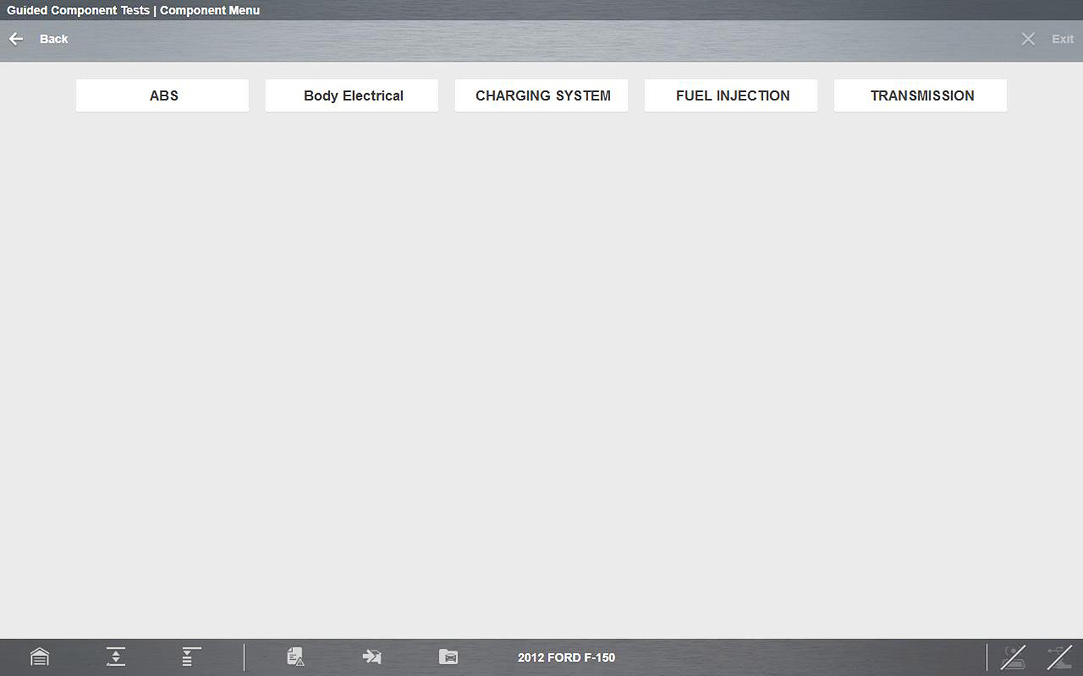
Once the vehicle is identified, a menu displays available systems and components to test.
|
2.
|
Make a selection to continue. |
Typical System menu options
|
3.
|
Continue to follow the screen prompts to make your desired selection. |
Final menu options include two typical selection types (descriptions are provided in the following sections):
Component Information
 Component Information
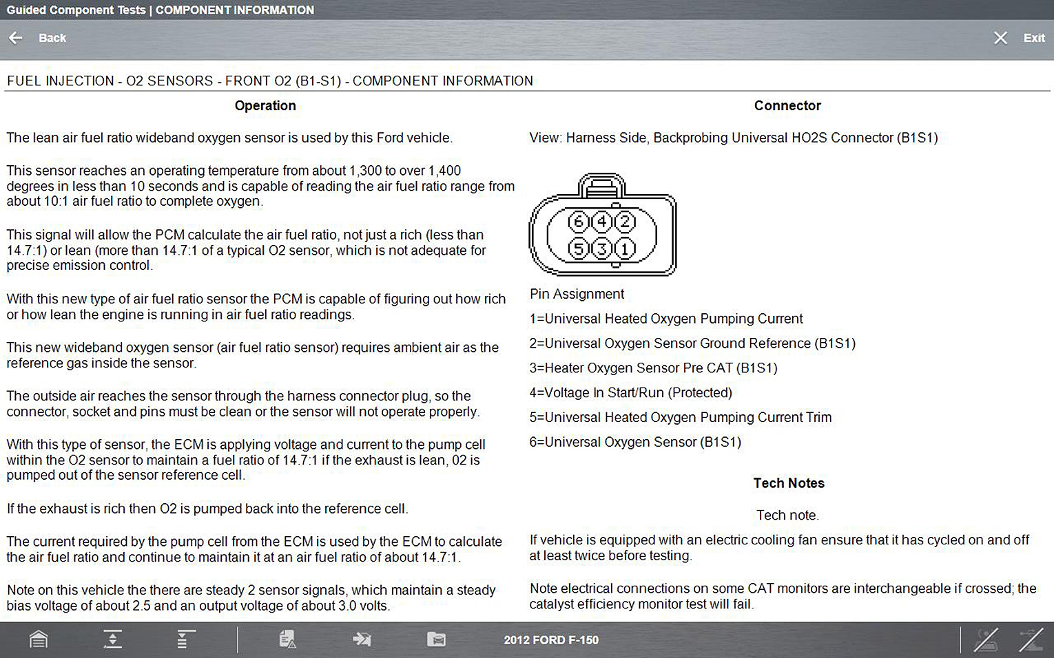
Component Information provides specific operational information (if available) on the selected component, and may also include electrical connector and pin location and function details
The Component Information screen contains information to assist you with testing, and is divided into sections:
|
●
|
Operation—provides a general description of normal component operation. |
|
●
|
Connector—displays the component connector and lists pin assignments. |
|
●
|
Location—identifies the component location and the best place for testing it. |
|
●
|
Tech note—provides Guided Component Test‑related tips (for example, common failures or faults) as well as update or recall information. |
Typical Component Information screen
Tests
 Tests
Tests
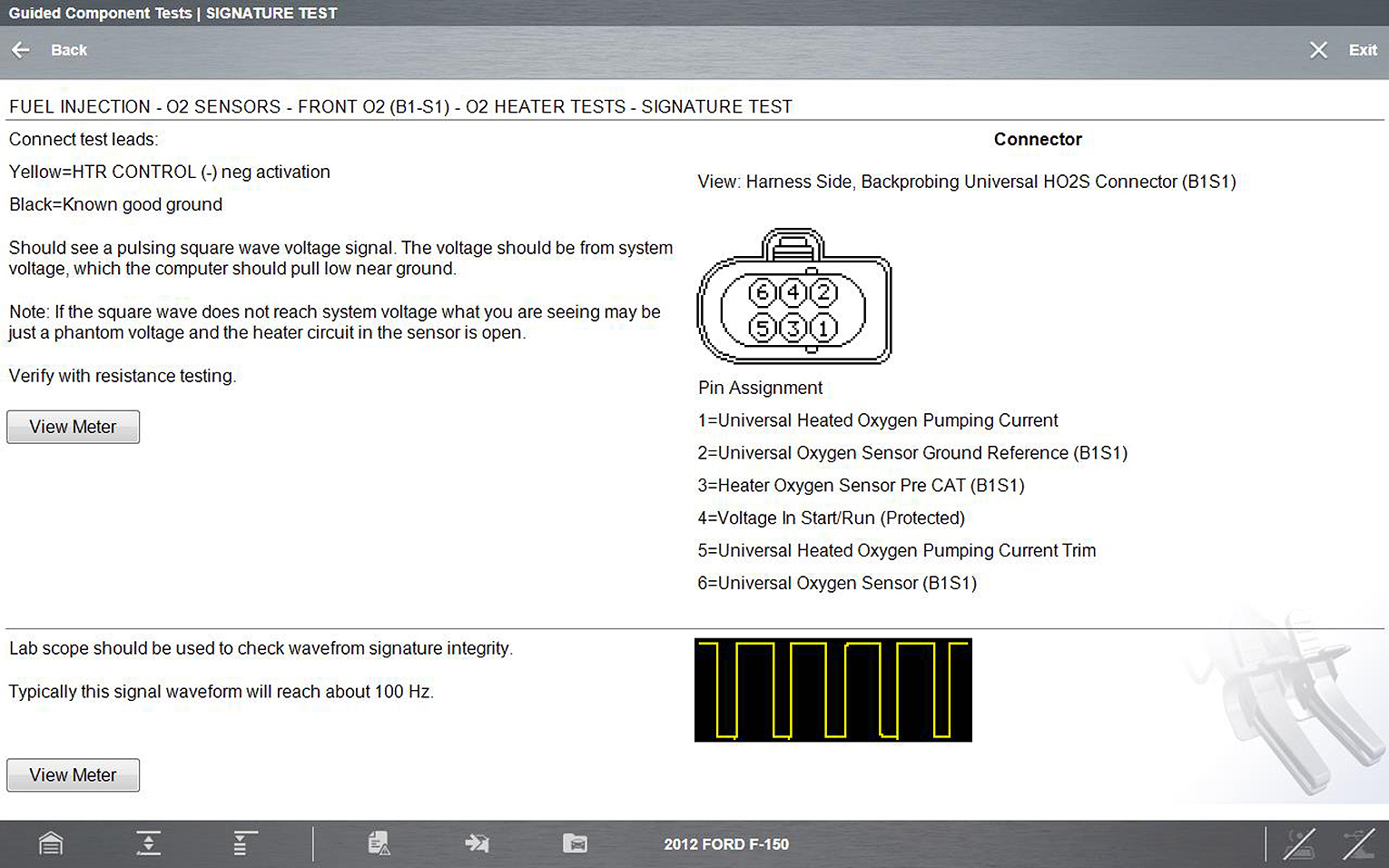
Tests provide specific instructions (if available) to help you perform tests on components. Selecting a component test opens a preconfigured meter to start the test, and typically also provides connection instructions, specifications, and testing tips.
A typical Test screen may contain multiple test options, and information to assist you perform the test.
Typical Signature Test screen
Test screens and menus will vary, and in some instances more than one selection may be available and/or open a submenu.
Test screens may contain icons and hyperlinks that link to other supporting information or open test screens. Common links are:
|
–
|
Show More Information—opens a new screen with additional information. |
View Meter
 View Meter
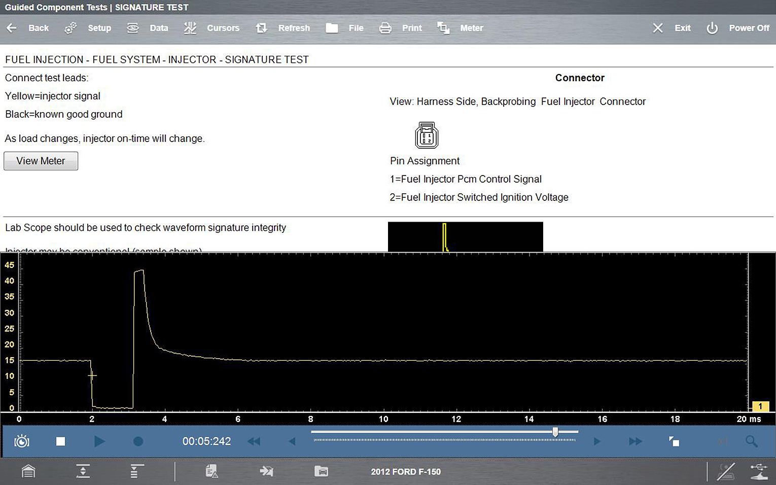
View Meter opens a live meter set up to perform the test in the lower portion of the screen . Once the meter view is open, the Guided Component Test toolbar at the top of the screen is replaced by the Scope Multimeter toolbar, which allows you to make adjustments to the settings. See Main Screen and Toolbars for toolbar icon information.
The Meter icon, is only available Guided Component Test view meter mode.
Sample view meter window
Three view meter options are available:
|
1.
|
With View Meter active, select the Meter icon on the toolbar once and the meter expands to fill the entire screen. |
|
2.
|
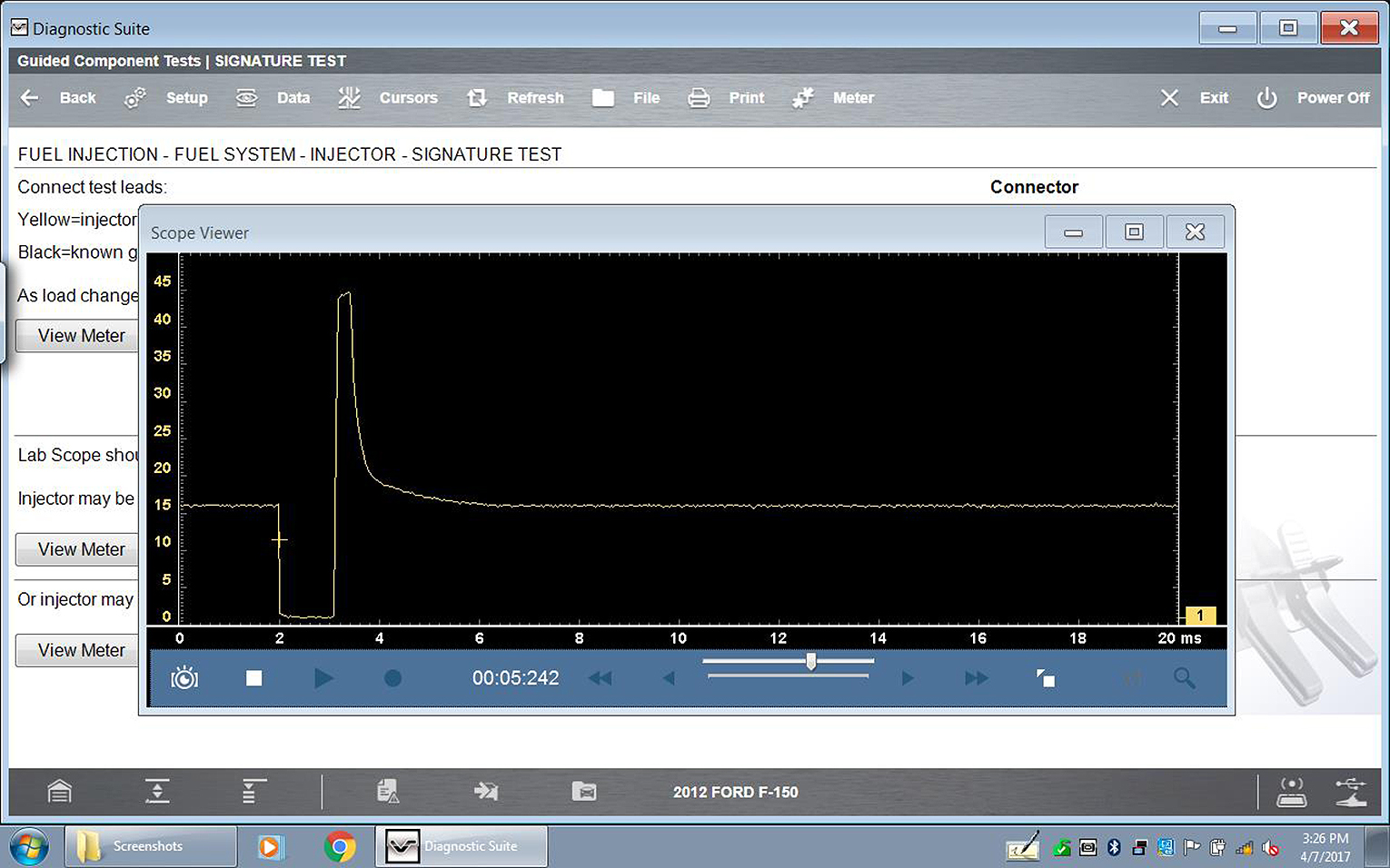
Select the Meter icon a second time and the meter will open as a separate window. This window can remain open if you switch to the Scan Module and can be accessed from the Windows toolbar at the bottom of the screen. You can also resize and reposition the meter window on the screen. |
Sample meter view in a separate window
Selecting the Close icon (X) when viewing the meter in a separate window closes the meter and returns you to the Guided Component Test screen.
|
3.
|
Select the Meter icon a third time to close the separate window and return to the standard meter view. |
Select Exit from the toolbar to close meter view and return to the Guided Component Test screen.
Performing a Test
 Performing a Test
To perform a Meter Test follow the on‑screen instructions to connect the test leads to the component. Follow the instructions carefully, as certain Guided Component Tests require the use of specific leads.
Once the leads are connected, select the View Meter icon to display the results. Review the on-screen information to verify the test results.
![]() Selecting Guided Component Tests provides you with an extensive collection of vehicle specific component tests and reference information for engine, transmission, ABS, charging, transfer case, and suspension systems. It is like having access to a complete library of automotive repair manuals for testing multiple vehicle components.
Selecting Guided Component Tests provides you with an extensive collection of vehicle specific component tests and reference information for engine, transmission, ABS, charging, transfer case, and suspension systems. It is like having access to a complete library of automotive repair manuals for testing multiple vehicle components. 
![]()
