Getting Started
Press and release the Power Button ![]() to turn the Thermal Imager ON. After the introductory screen displays, release the button.
to turn the Thermal Imager ON. After the introductory screen displays, release the button.
Press and hold the Power Button ![]() for a minimum of 2 seconds to power the Thermal Imager OFF.
for a minimum of 2 seconds to power the Thermal Imager OFF.
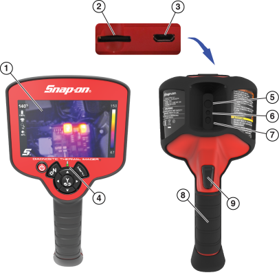
| 1. | Display |
| 2. | microSD (Secure Digital) Card |
| 3. | micro USB Jack |
| 4. | Battery Charging LED |
| 5. | Thermal Window |
| 6. | Visual Light Window |
| 7. | LED Spotlight |
Use the Key Pad Control Buttons to navigate the menus and toolbar.
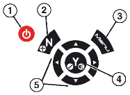
| 1. | Power Button |
| 2. | No / Cancel & Enable / Disable video recoding |
| 3. | Menu Button |
| 4. | Yes / Accept & LED Spotlight On / Off |
| 5. | Directional Control (Left/Right - View Setting Selection) (Up/Down - Overlay Setting Selection) |
For additional information see Features / Controls.
Press the Menu button to open the Menu screen.
For additional information see Using the Menu.
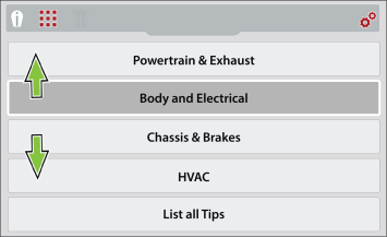
Use the Directional Control Buttons to navigate the Menu toolbar.

| 1. | Expert Tips |
| 2. | Image Gallery |
| 3. | Delete Image |
| 4. | Settings |
Use the Directional Control Buttons to navigate the menus.
After startup the Thermal Imager+ is in live capture mode. This allows you to make thermal measurements and capture still images and videos.
The temperature readout is not displayed for approximately 30 seconds upon startup. This is normal due to the unit automatically calibrating upon startup.
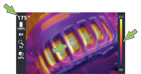
To take a thermal reading, position the point of interest in the center of the display on or near the target indicator (see image below). The target indicator measures the average temperature around the indicator, this numerical value is displayed in the upper left (see image below).
The temperature is also visually indicated within the color palette indicator on the right side (see image below). The color palette indicator shows the complete temperature range of the active measured scene including the minimum and maximum temperature values of the scene. This palette indicator is dynamic, and it is normal for the min/max temperature values to constantly change.
For additional information see Basic Operation.
Change Display Mode - Use the Left / Right control buttons ![]() to change display modes.
to change display modes.
| ● | 1X Zoom |
| ● | 2X Zoom |
| ● | Picture-in-Picture |
| ● | Diffused Beam |
| ● | Split Screen |
Change Opacity Level - Use the Up / Down control buttons ![]() to change opacity levels.
to change opacity levels.
| ● | From 0% (Visual Light) up to 100% (Full Thermal) in 20% steps. |
Adding Temperature Markers - Using the Freeze Image feature gives you the ability to add temperature markers to a captured image. These markers are useful when trying to display multiple temperature values, and save the image with the markers for future reference.
Taking a Picture- Activate the Trigger to save a still image ![]() of the active screen.
of the active screen.
Recording Video - Press the ![]() button to start video mode
button to start video mode ![]() , then pull the Trigger to start/stop recording.
, then pull the Trigger to start/stop recording.
Images and videos are automatically saved to the microSD card and can be viewed in the Gallery.
Using the LED Spotlight- Press the Y button to turn the LED spotlight ON/OFF.
Onscreen Navigational Tips - Tips are provided for select menu navigation procedures. Each tip will appear only once after turning on the Thermal Imager. Navigational Tips can be enabled or disabled.
| 1. | Turn on the thermal imager and press the Menu button. button. |
| 2. | From the toolbar select the Settings |
| 3. | Select Wi-Fi Connection from the menu. |
| 4. | If needed, turn Wi-Fi On using the UP control button to select the Wi-Fi Power icon, and the Y button to turn it On. |
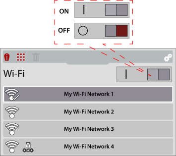
| 5. | Use the Down control button to navigate to the Wi-Fi network list, then use the Up / Down control buttons to select a wireless network. Press the Y button to enable the selection. |
| 6. | If a password is required when choosing a secured (protected)  network, enter the password using the on-screen keyboard and the directional control buttons. Select the “enter/ done” key when finished. network, enter the password using the on-screen keyboard and the directional control buttons. Select the “enter/ done” key when finished. |
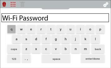
For additional information, see Connecting to Wi-Fi.
During Live mode operation activate the Trigger to automatically save and upload an image to your Snap-on Cloud account.
Before you can upload images from your Diagnostic Thermal Imager, you need to have a Snap-on Technician Profile and link your Diagnostic Thermal Imager to it. Find setup instructions for Snap-on Technician Profile at Snap-on Technician Profile Help*.
Ensure the Thermal Imager Wi-Fi is turned on and connected to a network when setting up your profile. For additional information, see Connecting to Wi-Fi.
Finding your authorization codes:
| 1. | Press the Menu button, then from the toolbar select the Settings button, then from the toolbar select the Settings |
| 2. | Select Snap-on Cloud Setup from the menu. |
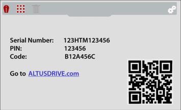
| 3. | Write down the Serial Number, PIN and Code that are displayed or leave the screen displayed while entering the information online. |
;
1. Press the Menu button, then select the Settings
![]() icon from the toolbar.
icon from the toolbar.
2. Select the Language menu option, and then select the desired language
The Thermal Imager is shipped with the battery installed and with a partial charge. It is recommended to fully charge the battery before use.
| ● | Connect the supplied USB cable to the micro USB jack on the top of the Thermal Imager, and to the USB power supply adapter. Connect the USB power supply adapter to a live power source. |
| ● | When the battery is charging, the LED on the front of the imager will be red . |
| ● | When the battery is fully charged the LED will turn green. |
For additional information, see Battery Charging.
See Application Examples for additional information.
| ● | Heated Seats |
| ● | Heated Steering Wheel |
| ● | Electrical Components (high current, resistance) |
| ● | A/C / Heater System |
| ● | Alternator Operation |
| ● | Exhaust Leaks |
| ● | Exhaust Manifold (misfire) |
| ● | Rear Defrost Operation |
| ● | Wheel Bearing Failure |
| ● | Tire Leaks |
| ● | Mechanical Friction |
| ● | Fluid Blockage |


