![]()
The Scanner function allows your diagnostic tool to communicate with the electronic control modules (ECMs) of the vehicle being serviced.
This allows you to perform tests, view diagnostic trouble codes (DTCs), and live data parameters from various vehicle systems such as the engine, transmission,
antilock brake system (ABS) and more.
Scanner is a menu driven application that communicates with vehicle control modules to access diagnostic trouble codes (DTCs), parameter data (PIDs), functional tests, and more. To navigate the application, use your fingertip or the stylus to make onscreen menu selections to access the desired data, test or function.
|
Learning Basic Scanner Operations Using Demonstration Mode Opens in a new tab. |
This section lists the basic scanner operation steps, and is only intended as a
quick-start reference. Refer to the supporting topics in this section for detailed operation information.
Menus, options and procedures may vary by vehicle. The following instructions apply to most OBD-II vehicles. Not all vehicles support the Auto ID and, or Instant ID feature.
| 1. | Turn the diagnostic tool on. |
| 2. | Turn the vehicle ignition switch on. |
| 3. | Connect the CSM to the vehicle DLC. |
The CSM must be paired to the diagnostic tool to communicate.
| 4. | Select Scanner from the Home screen. |
While using the Scanner and OBD-II/EOBD functions, on-screen connection instructions are provided. The instructions may include the location of the vehicle DLC.
| 5. | Depending on the vehicle, Instant ID may occur. See Identifying the Vehicle (below) for additional information. |
| 6. | If Instant ID is not supported, after selecting vehicle year and make, choose Automatic ID or Manual ID and enter the vehicle information at the screen prompts to continue. See Identifying the Vehicle (below). |
If Automatic ID is selected, the identification process automatically completes (if supported by the vehicle) after the vehicle make and year are manually entered.
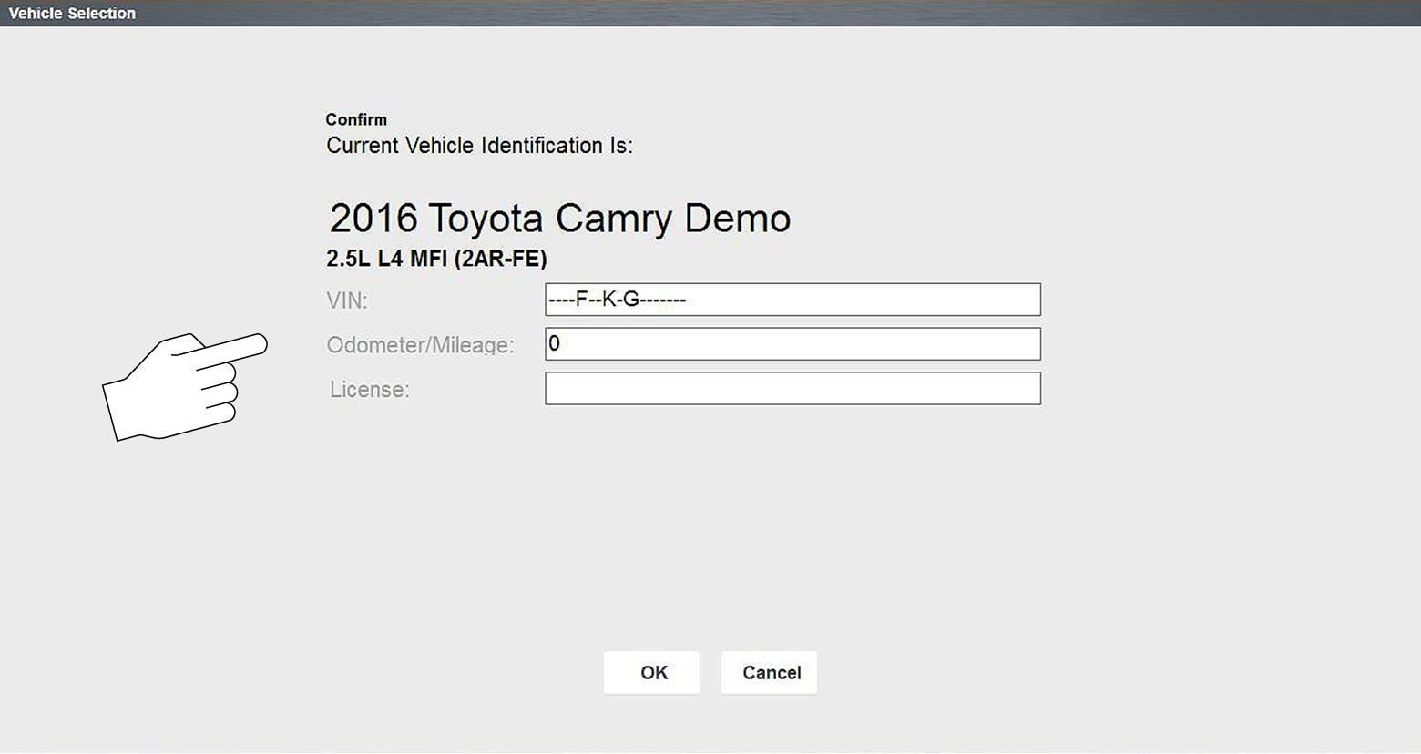
| 7. | Select OK to confirm the vehicle. If needed, enter the vehicle VIN, odometer reading and license plate. |
| 8. | Select a VehicleSystem (e.g. Engine). See Selecting a Vehicle System. |
If the CSM is not connected, an onscreen message may appear providing connection instructions.
| 9. | Select a Vehicle System Test/Function (e.g. Codes Menu) to perform. See Selecting a Vehicle System Test/Function. |
Connection of the CSM to the diagnostic tool and vehicle DLC is required for Scanner testing.
Vehicle identification is the initial step in using the Scanner function. Once vehicle identification information is entered it is saved in Vehicle History and can be selected again to save time when re-testing the same vehicle in the future.
Menus options and procedures may vary by vehicle.
Instant ID
Instant vehicle identification is a built-in (default) Scanner feature that will save you time when identifying a vehicle, by automatically communicating with the vehicle to complete the vehicle identification process. Depending on the vehicle, Instant ID may occur automatically and only ask you to confirm the vehicle, or additional screen prompts may be displayed to enter vehicle information.
To complete the Instant ID process and continue, select Continue from the vehicle confirmation screen.
Manual ID
If Instant ID is not supported, the vehicle identification must be manually entered. The vehicle identification sequence is menu driven, follow the screen prompts to enter the vehicle information.
To complete the Manual ID process and continue, select Continue from the vehicle confirmation screen.
Identifying a vehicle:
| 1. | Select Scanner from the Home screen. |
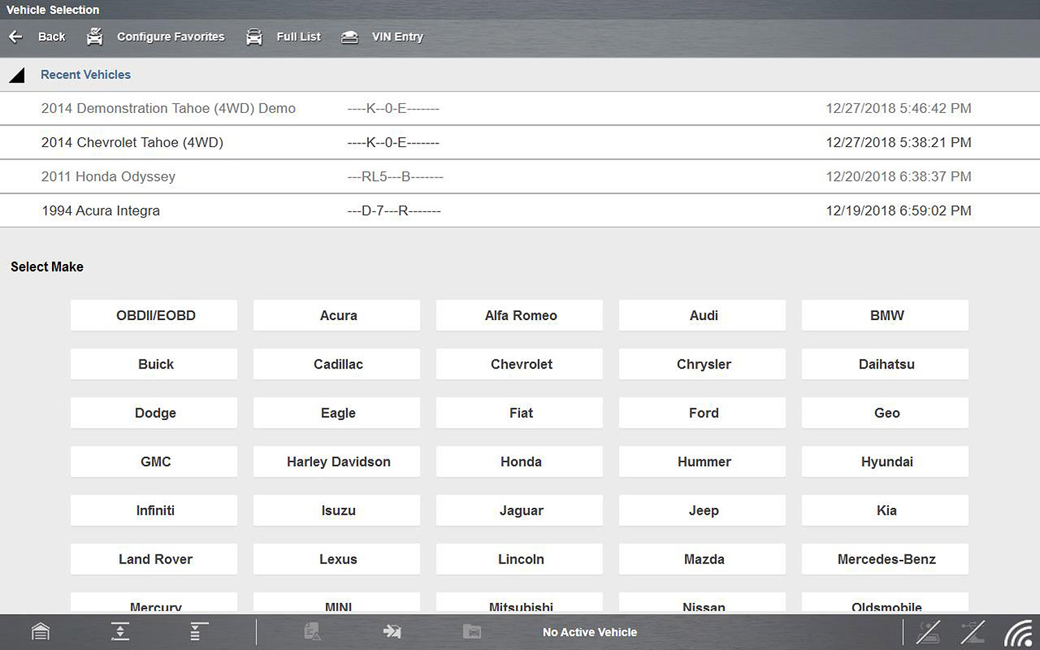
A list of vehicle manufacturers (makes) will display.
In addition, the last four scanned vehicles are listed at the top of the screen (Recent Vehicles) for quick-re-identification if needed.
Select the ![]() icons to expand/collapse the list.
icons to expand/collapse the list.
Typical - Manufacturer list
| 2. | Select a manufacturer or vehicle from the list. If a Recent Vehicle is selected, that vehicle will be re-activated. |
A model year menu will display.
You can limit the number of manufacturers that appear on the list by selecting Configure Favorites from the toolbar.
| 3. | Select the vehicle year. |
A list of vehicle types or models will display. Several selections may be required to identify the vehicle type and model, follow the screen prompts and enter the required information.
A confirmation page showing the identified vehicle will display once all the required data has been entered. If needed, enter the vehicle VIN, odometer reading and license plate. Review the information to make sure it is correct.
The VIN and license plate number are saved in the vehicle record and can be used in future search criteria when managing your files in the Snap-on Cloud.
| 4. | Select OK . |
Camera Scan Vehicle Identification
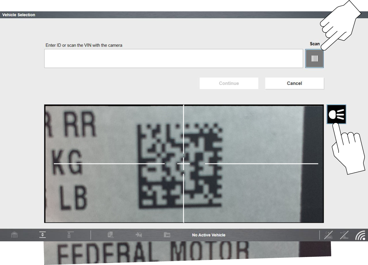
Depending on the vehicle, the vehicle’s VIN barcode or Data Matrix code may be scanned to identify the vehicle. The location of these codes will vary, however they can be commonly found on the drivers side door or door jamb.
| 1. | Select Scanner from the Home screen. |
| 2. | From the vehicle selection page, select VIN Entry from the upper toolbar. |
| 3. | Click the Scan icon to open the camera display. |
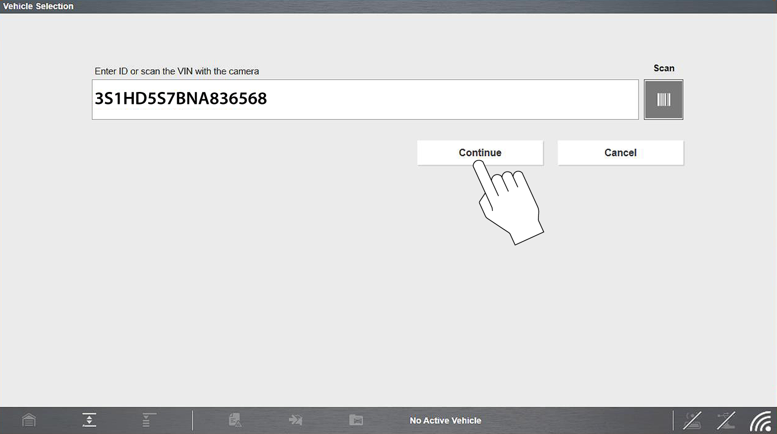
| 4. | Aim the cross-hair markers of the camera steady on the center of the code until the code is captured. When the code is successfully captured, a confirmation message is displayed and the VIN data field is populated with the vehicle VIN. |
If you are having trouble capturing the code, try:
| - | Turning the flashlight on/off (click icon) to achieve the best result. |
| - | Get as close to the code as possible, keeping it centred on the screen. |
| - | Hold the camera steady and allow the auto-focus to achieve a clear image. |
| 5. | Select Continue to exit and continue with the vehicle ID process. |
Occasionally, you may try to identify a test vehicle that the Scanner does not recognize, the database does not support, or has some unique characteristics that prevents it from communicating with the Scanner. In these instances, there is an alternate choice that allows you to establish communication with the vehicle:
| ● | OBDII/EOBDFunction—this function allows you to connect to the OBDII equipped vehicle and perform basic OBD-II or EOBD diagnostic functions, see OBD Direct - OBD-II/EOBD for additional information. |
| 1. | After the vehicle has been identified, the Systems menu will display available vehicle systems. |
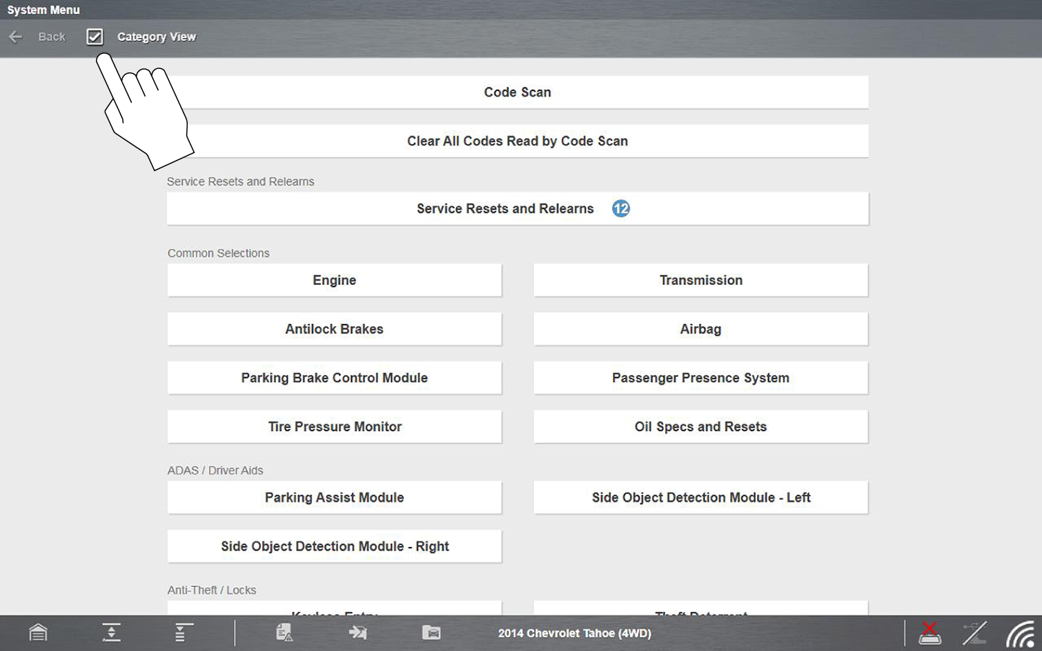
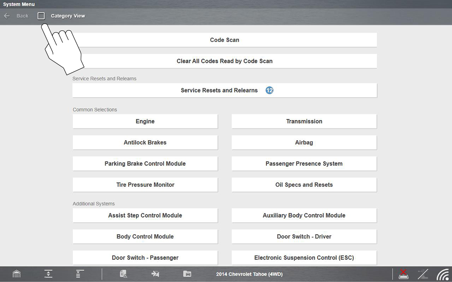
The System menu can be displayed in two views, by individual system categories or by common vehicle system categories. To change the view, select/deselect the Category View checkbox in the upper toolbar. Typical views are shown below.
| 2. | Select the desired vehicle system to continue. |
Not all vehicle systems may be supported by the vehicle, or available. Available systems will vary across vehicle manufacturers and models.
Typical vehicle system options may include:
| ● | Engine |
| ● | Transmission |
| ● | Antilock Brakes |
| ● | Airbag |
| ● | Body Control Module |
| ● | Instrument card |
| ● | Tire Pressure Monitor |
Typical - System Menu “Category View” Selected
Typical - System Menu “Category View” Not Selected
Special vehicle system options may include:
| ● | Code Scan |
| ● | Clear All Codes Read by Code Scan |
| ● | Service Resets and Relearns |
| ● | Oil Specs and Resets |
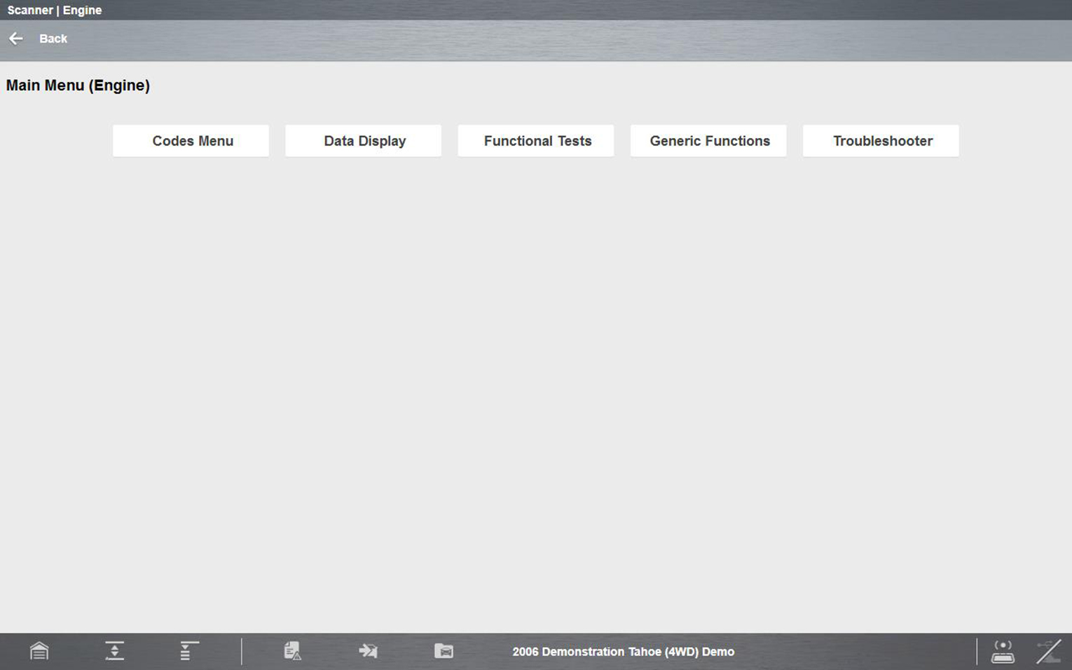
After a vehicle system is selected the vehicle system main menu will display available tests and/or functions. Select the desired option to continue.
Typical - Main menu (Engine shown)
Not all vehicle system test/functions may be supported by the vehicle, or available. Available system test/functions will vary across vehicle manufacturers and models.
Typical vehicle test/function options may include:
| ● | Codes Menu |
| ● | Clear Codes |
| ● | Data Display |
| ● | Generic Functions |
| ● | Functional Tests |
| ● | Troubleshooter |
| ● | Actuator Tests—similar to functional tests, checks the operation of certain actuators, such as solenoid valves and relays. |
| ● | Memory Resets—allows you to reprogram adaptive values for certain components after making repairs. Selecting opens a submenu. These options are found on the Functional Tests Menu for some models. |
| ● | System Tests—provides specific subsystem testing. Performing these tests is similar to functional tests. |
Actual onscreen test/function names may vary.
To exit Scanner, you must first terminate communication with the vehicle. The Scanner function will remain open as long as there is an active communication link with the vehicle.
A warning message displays if you attempt to exit before terminating communication with the vehicle. Damage to the vehicle’s control modules may occur if communication is abnormally disrupted. Make sure the CSM is properly connected at all times when communicating with a vehicle. Always exit all tests properly, and return to the Home screen before disconnecting the CSM, and before turning off the diagnostic tool.
Before disconnecting the diagnostic tool from the vehicle, Scanner communication must be terminated.
| 1. | As applicable, end any test being performed, and then select the Exit  or Back or Back  icon from the upper toolbar. icon from the upper toolbar. |
| 2. | Continue to select the Back icon until the “stopping communication” message is displayed. |
| 3. | Select the Change Vehicle icon |
The vehicle description on the lower toolbar will change to display “No Active Vehicle”.
| 4. | Select the Home icon  on the lower toolbar, to return to the Home screen. on the lower toolbar, to return to the Home screen. |
| 5. | Disconnect the CSM from the vehicle DLC. |
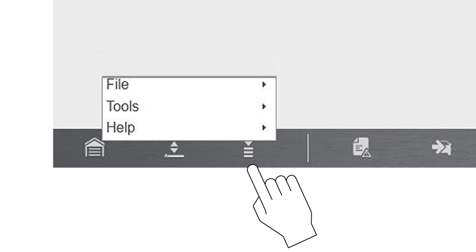
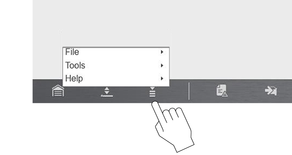
The following Menu options are available:
| ● | File—allows you to print or save the data being viewed. |
| ● | Tools—allows you to perform certain maintenance operations and adjust tool settings. |
| ● | Help—see Help (below) |
Menu icon (menu)
File
Use to print or save a copy of the data currently being viewed. Menu options include:
| ● | Save—opens a submenu with these options: |
| – | Screenshot—saves a graphic image of the current screen. |
| – | Collected Data—saves a recording of all the data currently in the buffer plus the number of frames designated after the trigger event. |
| ● | Print—opens a submenu with these options: |
| – | Screen—sends the current screen image to a printer. |
| – | Troubleshooter—prints the full text of the troubleshooter topic shown in the main body. |
Selecting an option opens a Windows Print dialog box for printing or saving the file. See Printing / Printer Setup.
Tools
This option (only available from within Scanner) allows you to adjust tool settings to your personal preferences. Selecting Tools opens a menu with two options:
| ● | Units Setup - Changing the Units of Measurement |
| ● | Display BEN |
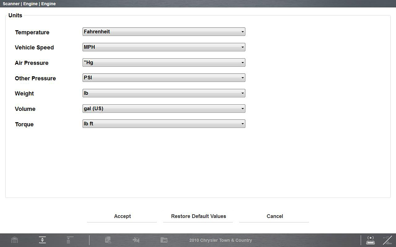
The Diagnostic Suite units of measurement can be changed for temperature, vehicle speed, air pressure and other pressure readings. Choose between US customary or metric units of measure.
| 1. | Select Scanner.. |
| 2. | Select the Menu icon from the lower toolbar. |
Menu icon
| 3. | Select Tools > Units Setup.. |
The Units setup dialog box opens.
Units Setup screen
| 4. | Use the dropdown menus to select the desired value for each item. |
| 5. | Select Accept to close the dialog box and apply the changes. |
Selecting this option displays the Balco Engine Number (BEN) of the currently identified vehicle. In the event you contact customer service about a Scanner data issue, you may be asked to provide the BEN for reference to help in troubleshooting the issue.
Menu options include:
| ● | About Scanner Hardware Version - This option opens a dialog box showing the hardware version and other details about the Scanner function. A Copy to Clipboard icon allows you to paste the information to a document or e-mail. |
| ● | About Scanner This option opens a dialog box that shows the software version and other Scanner function details. A Copy to Clipboard icon allows you to paste the information to a document or e-mail. |
The Version Info, and Activation Status options are the same as explained previously, see Menu Icon for details.
To learn more about how to connect this diagnostic tool to vehicles using a secured gateway. See Security Link™ (opens new tab)
To protect against unauthorized vehicle network manipulation that may put car systems and customers at risk, many automobile manufacturers require authorized scan tool access to perform necessary diagnosis and repair. To learn more about how to connect this diagnostic tool to vehicles using a secured gateway visit www.snapon.com/gateway
Camera images and screenshots that are taken while a vehicle is selected (active) in Scanner, will be associated with that vehicle. A link to the files can be found in that vehicle’s “vehicle record” on the Attachment panel, see Vehicle History.
All images and screenshots are also uploaded to the Snap-on Cloud automatically when they are created. See Snap-on Cloud (new tab) for more information on using the Snap-on Cloud.
